Supercharge Your Innovation With Domain-Expert AI Agents!

Load limiting seatbelt retractor

A seat belt retractor and reel technology, applied in the field of vehicles, can solve problems such as discomfort and resistance to load

Inactive Publication Date: 2018-11-13
FORD GLOBAL TECH LLC
View PDF0 Cites 0 Cited by
  • Summary
  • Abstract
  • Description
  • Claims
  • Application Information

AI Technical Summary

Problems solved by technology

The combination of sudden locking and occupant inertia can cause the webbing to place a resistive load on the occupant sufficient to cause occupant discomfort

Method used


Image

  • Load limiting seatbelt retractor
  • Load limiting seatbelt retractor
  • Load limiting seatbelt retractor

Examples


Embodiment Construction

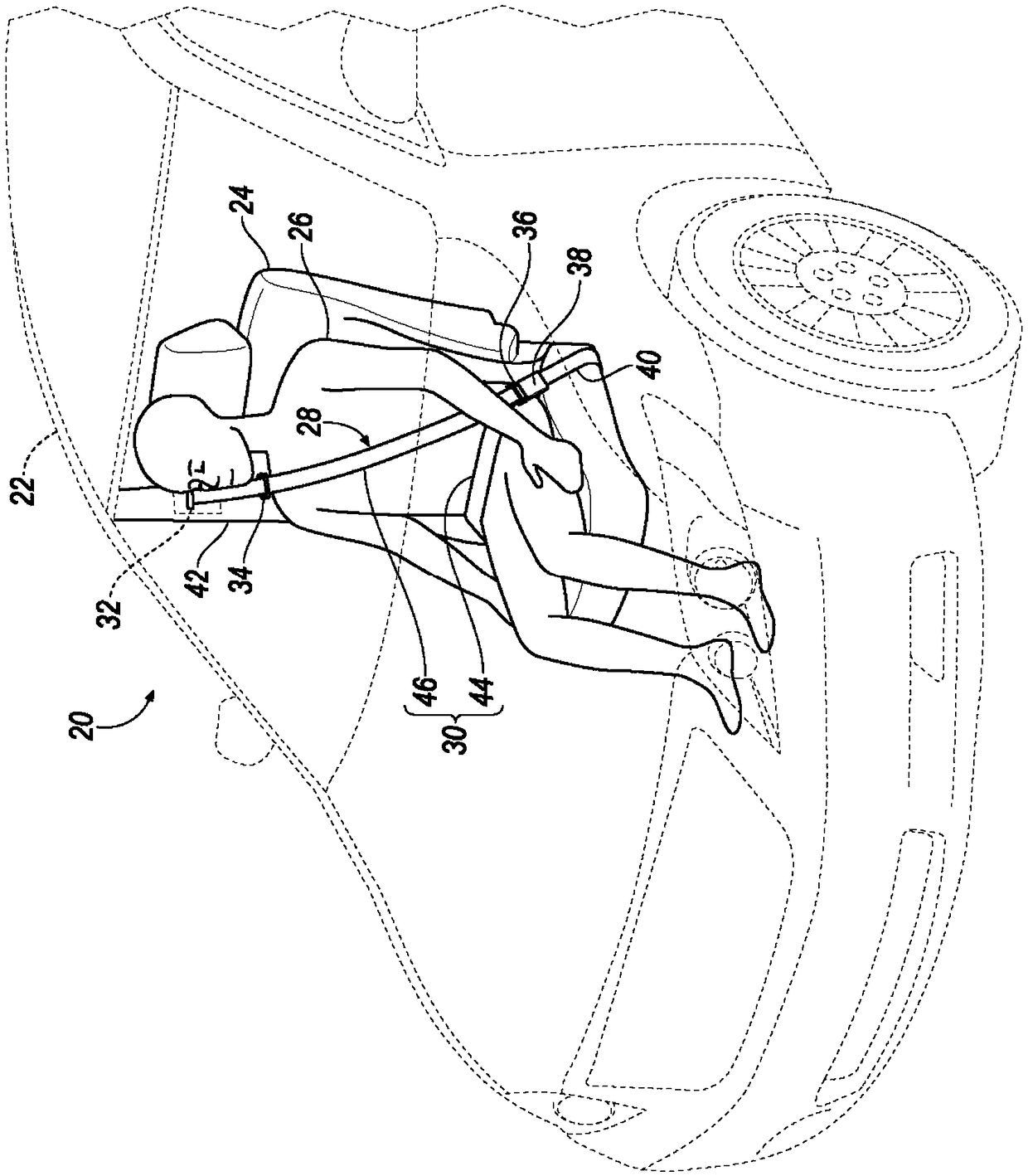
[0046] In this description, relative orientations and directions (e.g., up, down, bottom, forward, backward, front, rear, rear, outside, inside, inward, outward, sideways, left, right) are not intended to be limiting, Rather, at least one embodiment of the structure is described for the convenience of the reader. Such an example orientation is from the perspective of an occupant seated in the seat facing the dashboard. In the drawings, like reference numerals designate like parts throughout the several views.

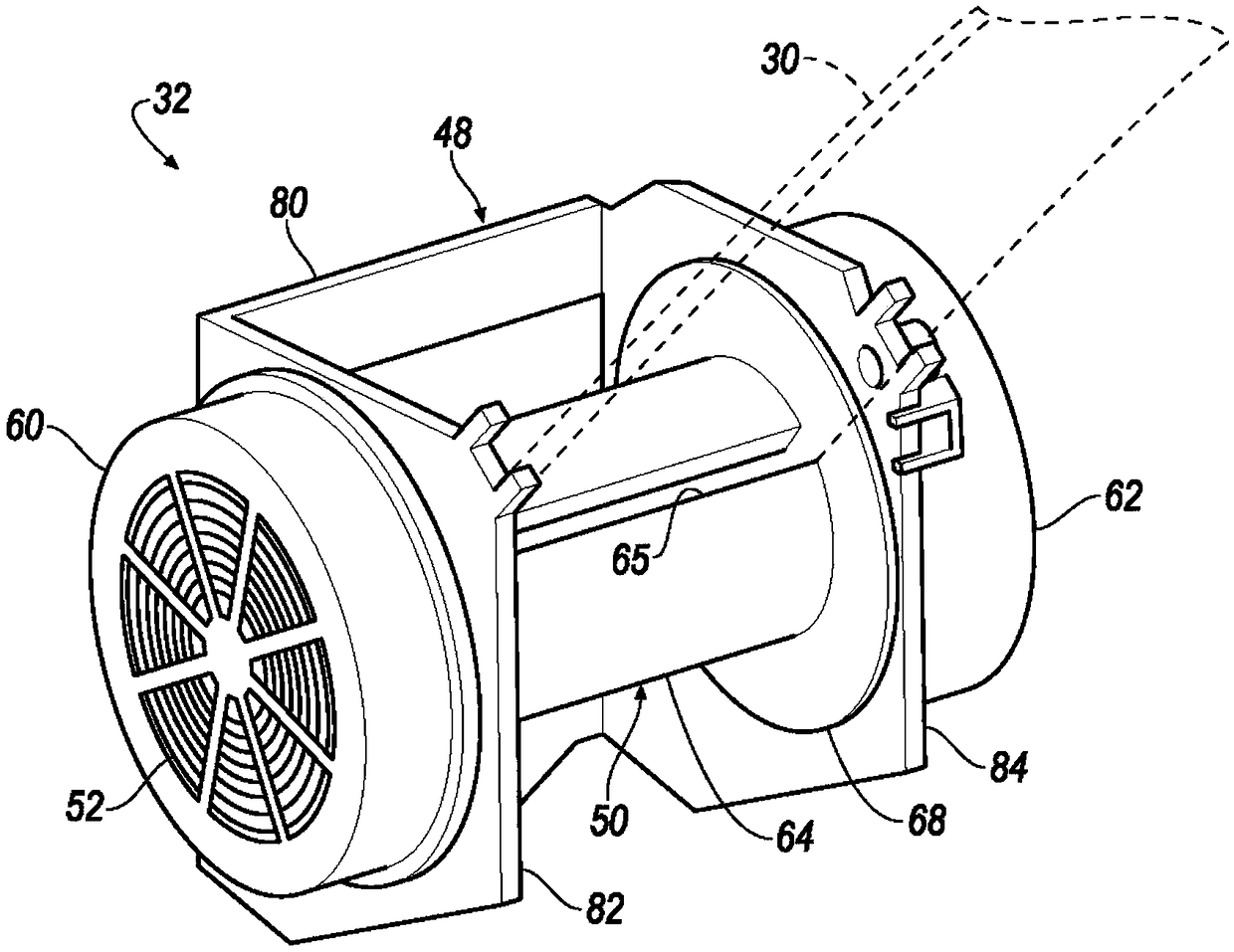
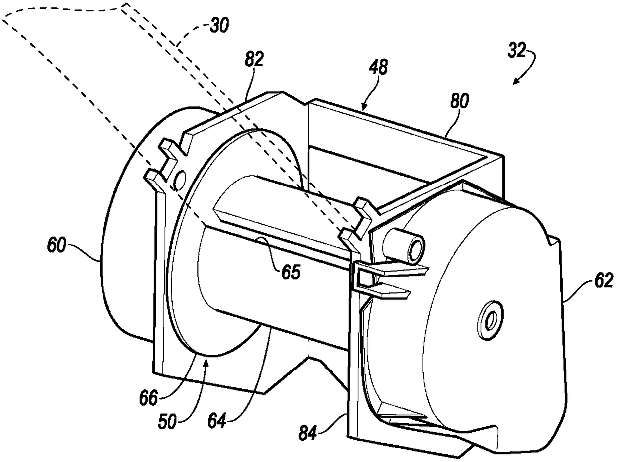
[0047] The seat belt retractor includes a base, a reel, a cylinder and a cylinder lock. The reel is rotatably connected to the base and has a piston portion. The cylinder engages the piston portion and defines a first chamber therewith. The piston portion is movable from a first position producing a first chamber volume to a second position producing a second chamber volume. A cylinder lock in a first state rotatably secures the cylinder to the base. A damping flui...


PUM


Abstract

A seatbelt retractor includes a base, a spool, a cylinder and a cylinder lock. The spool is rotatably coupled to the base and has a piston portion. The cylinder is engaged with the piston portion andtherewith defines a first chamber. The piston portion is movable from a first position yielding a first chamber volume to a second position yielding a second chamber volume. The cylinder lock in a first condition rotatably fixes the cylinder to the base. Damping fluid is disposed in the chamber.

Description

technical field [0001] The invention relates to the technical field of vehicles, in particular to a load limiting safety belt retractor. Background technique [0002] The seat belt system may include a retractor for unwinding the seat belt webbing. The retractor includes a spool around which the webbing is wound. When the webbing is fastened by the seat occupant, the webbing unwinds from the spool. In the event of a vehicle crash, the spool is locked to prevent it from rotating and prevent further unwinding of the webbing. The sudden locking combined with the occupant's inertia may cause the webbing to place a resistive load on the occupant sufficient to cause occupant discomfort. A load limiting mechanism within the retractor allows a cushioned termination of webbing travel to reduce this discomfort. Known load limiting mechanisms include a torsion bar positioned centrally on the spool. The torsion bar may be a cylindrical steel rod having a yield strength selected to ...

Claims


Application Information

Patent Timeline
IPC IPC(8): B60R22/34B60R22/46
CPCB60R22/34B60R22/4628B60R2022/282B60R22/341B60R22/3413B60R22/4676B60R22/36F16F9/06F16F9/10F16F9/30F16F2222/08F16F2224/046F16F2224/048
Inventor 穆罕默德·奥玛·法鲁克詹姆斯·郑·质罗伯特·威廉·麦克科伊萨伊德·大卫·巴尔巴特迪恩·M·贾拉迪
Owner FORD GLOBAL TECH LLC
Features
  • R&D
  • Intellectual Property
  • Life Sciences
  • Materials
  • Tech Scout
  • Unparalleled Data Quality
  • Higher Quality Content
  • 60% Fewer Hallucinations
Learn More