
Lacing device

A lacing and integrated technology, applied in the field of lacing devices based on rotor and stator, can solve the problems of low production efficiency, low lacing tensile strength, complex structure, etc.

Pending Publication Date: 2018-11-13
ICOMWELL INTELLIGENT MEDICAL TECH CO LTD
View PDF10 Cites 2 Cited by
  • Summary
  • Abstract
  • Description
  • Claims
  • Application Information

AI Technical Summary

Problems solved by technology

[0002] Although there are many kinds of lacing systems, most of the existing lacing systems have complex structures, low efficiency of internal space utilization, low lacing strength, low production efficiency, troublesome threading during use, and difficult maintenance and replacement when damaged. question
[0003] The invention provides a lacing system based on a stator and a rotor and its use method, which solves the above problems of complex structure, low utilization efficiency of internal space, low tensile strength, low production efficiency, troublesome threading during use, and difficult maintenance and replacement when damaged.

Method used


Image

  • Lacing device
  • Lacing device
  • Lacing device

Examples


Embodiment 1

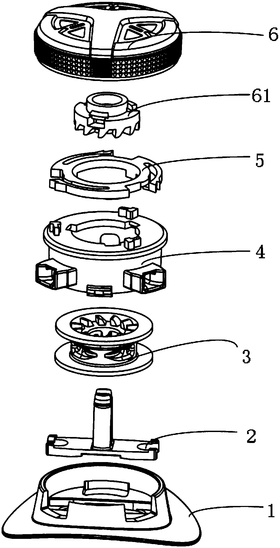
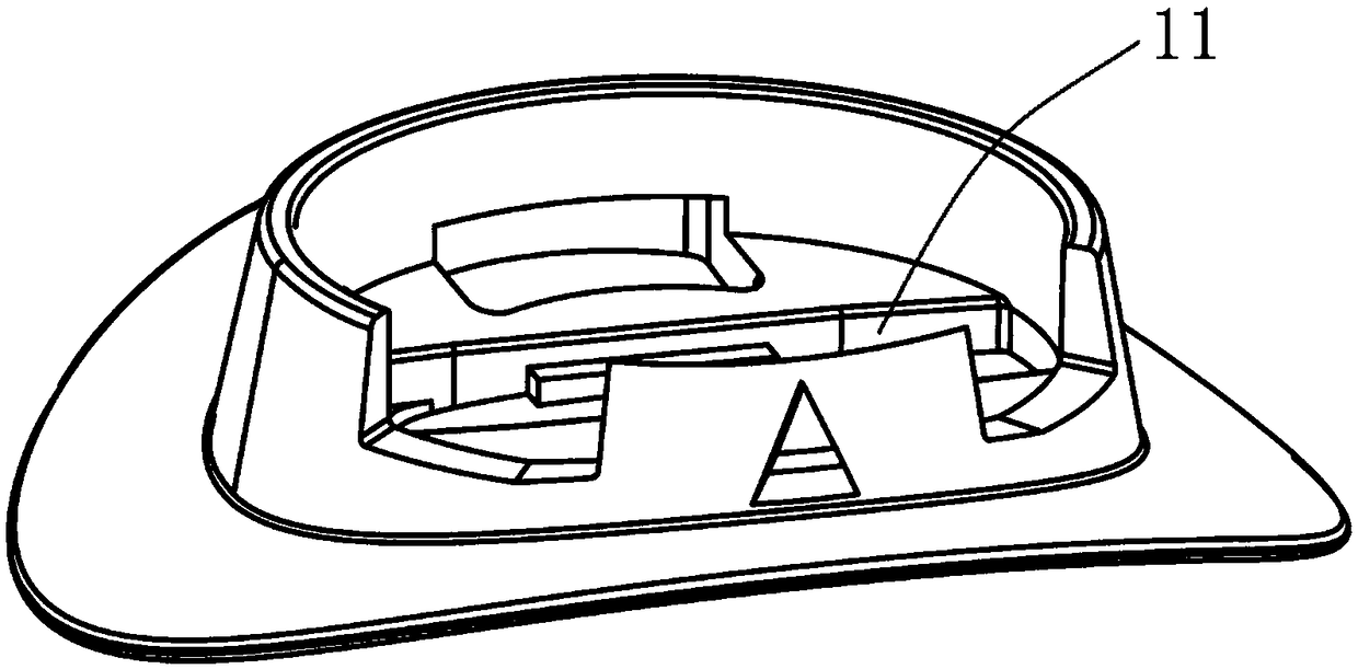
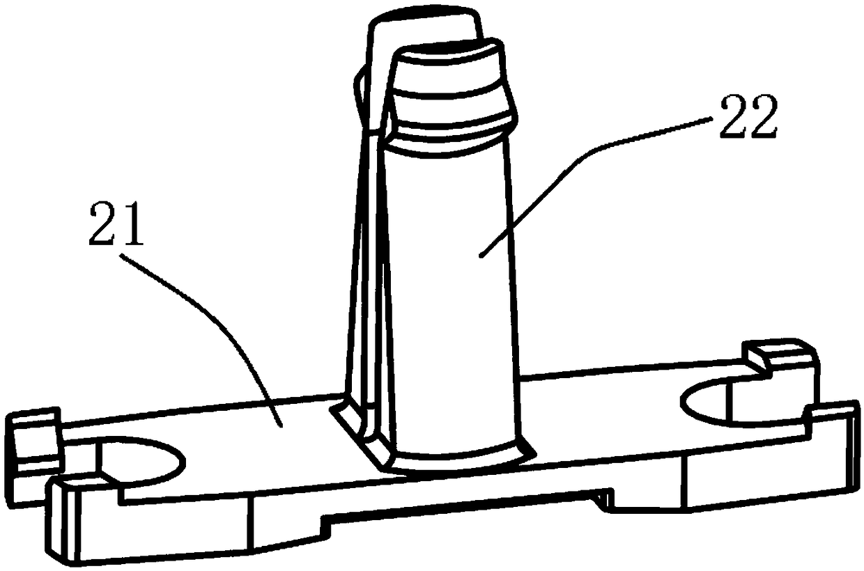
[0085] Such as figure 1 As shown, a lacing device includes a base 1, an elastic stop pin 2, a winding groove 3, a sleeve 4, a pawl ring 5 and an upper cover 6, and the base 1 can be fixedly arranged on the upper, the tongue, the heel , coat or luggage, such as figure 2 As shown, the base 1 is provided with a through hole 11; as image 3 As shown, the elastic retaining pin 2 includes a fixing part 21 matching the through hole 11 and a retaining pin 22 arranged on the fixing part 21. The fixing part 21 of the elastic retaining pin 2 fits with the bottom of the sleeve 4 and is installed in the through hole. 11, the stop pin 22 of the elastic stop pin 2 is located in the cavity formed by the sleeve 4; the sleeve 4 is detachably installed on the base 1, as Figure 4 As shown, the side of the sleeve 4 is provided with a first threading hole 41, a second threading hole 42 and a third threading hole 43 for threading out the cable belt. 5 fixed connections.

[0086] Such as Figu...


PUM


Abstract

The invention discloses a lacing device. The lacing device comprises a rotor and a stator. The stator comprises a sleeve. The rotor comprises an upper cover and a wire winding groove, wherein the cover and the wire winding groove are arranged from top to bottom in sequence. A pallet is arranged on the sleeve. Teeth are correspondingly arranged on the upper cover. Gear structures are arranged bothon the rotor and the stator respectively. The pallet and the teeth achieve engagement or separation connection through the gear structures. The lacing device has the advantages of being high in strength, small in size, convenient to use and the like.

Description

technical field [0001] The invention relates to the field of lacing devices, in particular to a lacing device based on a rotor and a stator and a use method thereof. Background technique [0002] Although there are many kinds of lacing systems, most of the existing lacing systems have complex structures, low efficiency of internal space utilization, low lacing strength, low production efficiency, troublesome threading during use, and difficult maintenance and replacement when damaged. question. [0003] The invention provides a lacing system based on a stator and a rotor and its use method, which solves the above problems of complex structure, low utilization efficiency of internal space, low tensile strength, low production efficiency, troublesome threading during use, and difficult maintenance and replacement when damaged. . Contents of the invention [0004] A lacing device includes a rotor and a stator, the stator includes a sleeve, the rotor includes an upper cover ...

Claims


Application Information

Patent Timeline
Patent Type & Authority Applications(China)
IPC IPC(8): B65B13/18
CPCB65B13/185B65B13/186
Inventor 黄伟
Owner ICOMWELL INTELLIGENT MEDICAL TECH CO LTD
Learn More