Circular high-accuracy crane and control method thereof

A high-precision, crane technology, used in cranes, trolley cranes, traveling mechanisms, etc., can solve the problems of easy accidents and low efficiency, and achieve the effect of improving the working range, simple principles, and reducing production accidents.

Active Publication Date: 2018-11-13
合肥市春华起重机械有限公司
View PDF7 Cites 3 Cited by
  • Summary
  • Abstract
  • Description
  • Claims
  • Application Information

AI Technical Summary

Problems solved by technology

Crane work usually judges whether the lifted object has reached the designated position by human eyes. In the actual production process, the efficiency is low and accidents are prone to occur.

Method used


Image

  • Circular high-accuracy crane and control method thereof
  • Circular high-accuracy crane and control method thereof
  • Circular high-accuracy crane and control method thereof

Examples


Embodiment 1

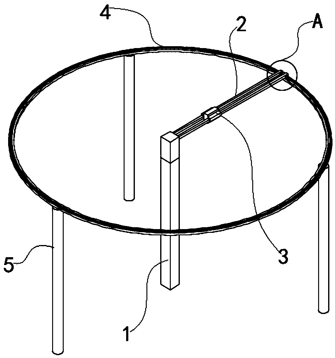
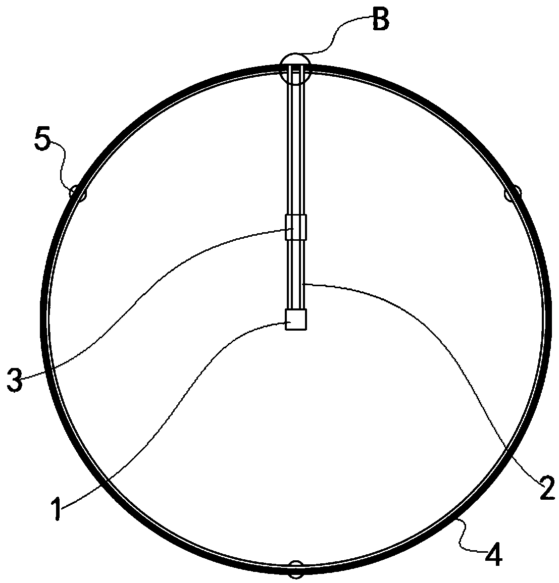
[0040] see Figure 1-10 As shown, the present invention is a circular high-precision crane, including a main frame 1, a slide bar 2, an electric hoist 3, a guide rail 4 and a sub-frame 5; the main frame 1 includes a rotary table 101 and a fixed frame 102; one end of the fixed frame 102 Connected with the rotary table 101; one surface of the rotary table 101 is connected with the slide bar 2, and the rotary table 101 drives the slide bar 2 to rotate; the slide bar 2 is provided with a matching electric hoist 3; one end of the slide bar 2 is connected with the guide rail 4; the guide rail 4 One surface is connected with several sub-frames 5 .

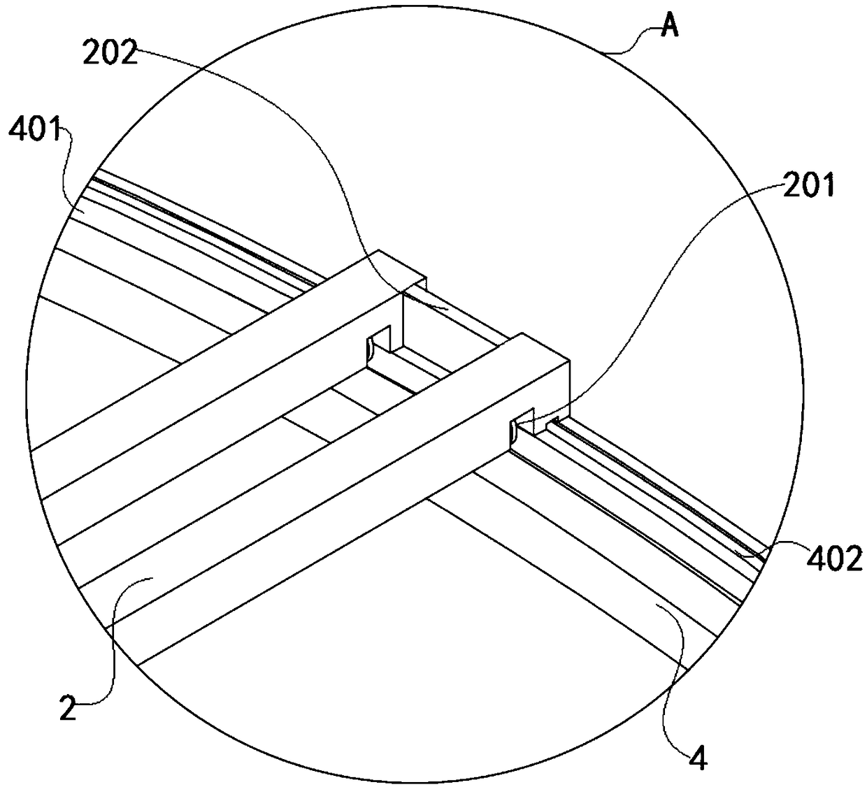
[0041] Such as figure 2 , 4 , 6, and 8, one end of the slide bar 2 is provided with a slot 201; a pulley 203 is fixed in the slot 201 to reduce the frictional resistance between the slide bar 2 and the guide rail 4, and reduce energy consumption; one end of the slide bar 2 is fixed with a fixed plate 202 One surface of the fixed plate...

Embodiment 2

[0049] see Figure 12As shown, a control method of a circular high-precision crane includes the following steps:

[0050] SS01: After power-on, the angle positioning sensor 403 positions the direction of the slide bar 2 and sets it as the initial direction, and the distance positioning sensor 206 positions the distance between the electric hoist 3 and the rotary table 101 and sets it as the initial distance;

[0051] SS02: Input the position of the heavy object to be lifted, the distance between the heavy object to be lifted and the rotary table 101 is the end distance, the end distance minus the initial distance is the moving distance, and the direction of the line between the rotary table 101 and the heavy object to be lifted is End direction, the clockwise angle from the initial direction to the end direction is the rotation angle;

[0052] SS03: The rotary table 101 drives the slide bar 2 to rotate clockwise at the rotation angle;

[0053] SS04: The electric hoist 3 slid...


PUM


Abstract

The invention discloses a circular high-accuracy crane and a control method thereof, and relates to the technical field of cranes. The circular high-accuracy crane comprises a main frame, a slide rod,an electric block, a guide rail and auxiliary frames, wherein the slide rod is connected with the main frame; the electric block is installed on the slide rod; one end of the slide rod is connected with the guide rail; one surface of the guide rail is connected with the plurality of auxiliary frames; a plurality of distance location sensors are installed on one surface of the slide rod; a baffleplate is installed on one surface of the electric block; the baffle plate is cooperated with the distance location sensors; a plurality of angle location sensors are arranged on one surface of the guide rail; a reflection plate is fixed to one end of the slide rod; and the reflection plate is cooperated with the angle location sensors. According to the circular high-accuracy crane, the working range of the crane is expanded through an annular design; the hoisting weight of the crane is increased through the cooperation of the guide rail and the auxiliary frames; and the hoisting position of the crane is accurately determined through the cooperation of the angle location sensors and the distance location sensors, so that the working efficiency is increased, and production accidents are reduced.

Description

technical field [0001] The invention belongs to the technical field of cranes, in particular to a circular high-precision crane and a control method thereof. Background technique [0002] With the development of my country's industrialization, cranes are widely used in various manufacturing and transportation industries. At present, common cranes are mainly divided into light and small lifting equipment, bridge type (bridge type, gantry crane), jib type (self-propelled, tower type, portal type, railway type, pontoon type, mast type) according to the structure. Crane) and cable type. Crane work usually judges whether the lifted object has reached the designated position by human eyes. In the actual production process, the efficiency is low and accidents are prone to occur. Contents of the invention [0003] The object of the present invention is to provide a circular high-precision crane and its control method. The working range of the crane is improved through the ring-s...

Claims


Application Information

Patent Timeline
Patent Type & Authority Applications(China)
IPC IPC(8): B66C19/00B66C13/46B66C7/08B66C9/04
CPCB66C7/08B66C9/04B66C13/46B66C19/00
Inventor 梁大伟
Owner 合肥市春华起重机械有限公司
Why Eureka
Try Eureka