Precise lifting mechanism for installation of large valve

An installation and valve technology, applied in the direction of lifting devices, lifting frames, hand-held tools, etc., can solve problems such as difficult alignment of positions, tiring and troublesome lifting of valves, etc., to reduce manual labor and facilitate manual installation. Effect

Inactive Publication Date: 2018-11-13
DONGGUAN LIANZHOU INTPROP OPERATION MANAGEMENT CO LTD
View PDF4 Cites 4 Cited by
  • Summary
  • Abstract
  • Description
  • Claims
  • Application Information

AI Technical Summary

Problems solved by technology

[0002] When installing existing valves, especially some large-volume valves, it needs to be lifted to the same height as the installation place, and then manually installed, which generally requires multiple people to operate, which is very troublesome and efficient Very low, manually lifting the valve is very tiring, and the position is not easy to align

Method used


Image

  • Precise lifting mechanism for installation of large valve
  • Precise lifting mechanism for installation of large valve

Examples


Embodiment Construction

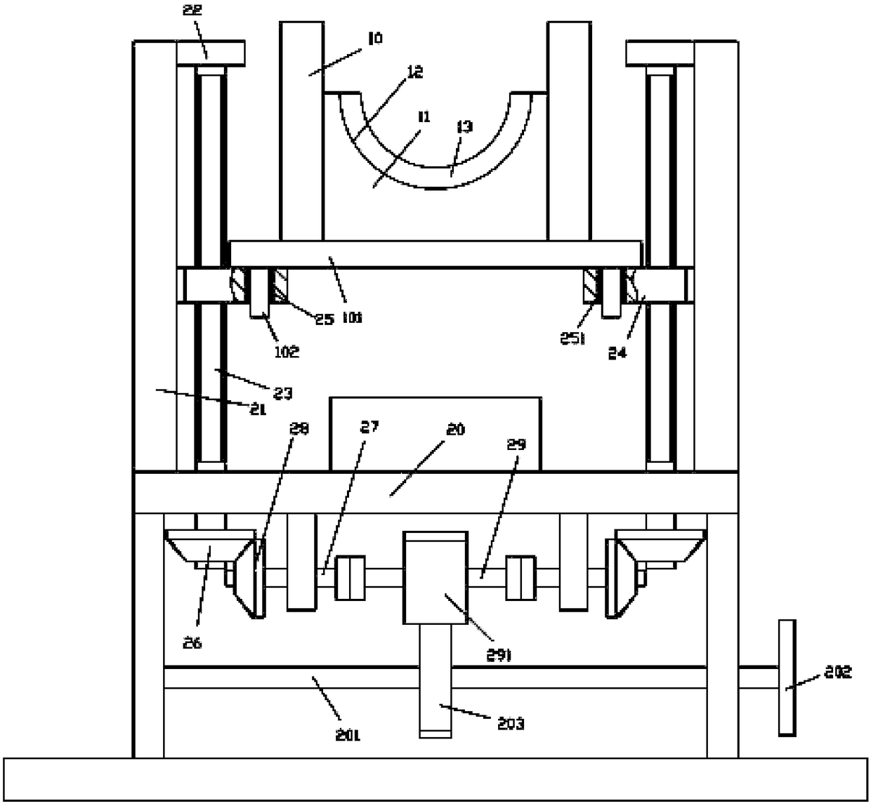
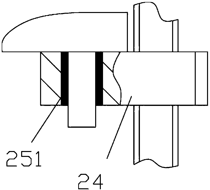
[0014] Examples, see e.g. Figure 1 to Figure 2 As shown, a precision lifting mechanism for large-scale valve installation includes an underframe 20, vertical support plates 21 are fixed on the left and right sides of the top plate of the underframe 20, and the top inner walls of the two vertical support plates 21 are fixed Horizontal plate 22 is arranged, and two vertical screw rods 23 are positioned at the left and right sides of the top plate of bottom frame 20, and the bottom end of vertical screw rod 23 is hinged on the top plate of bottom frame 20, and the top end of vertical screw rod 23 is hinged on the horizontal plate 22 , the vertical screw 23 is screwed with a lifting block 24, the bottom surface of the main base plate 101 is pressed against the top surfaces of the two lifting blocks 24, the left and right sides of the main base plate 101 are fixed with vertical guide columns 102, and the vertical guide columns 102 The sleeve is inserted into the positioning throug...


PUM


Abstract

The invention discloses a precise lifting mechanism for installation of a large valve. The precise lifting mechanism for installation of the large valve comprises a bottom frame. The left side and theright side of a top plate of the bottom frame are fixedly provided with vertical supporting plates. The inner side walls of the top ends of the two vertical supporting plates are fixedly provided with transverse plates. Two vertical threaded rods are located on the left side and the right side of the top plate of the bottom frame. The bottom ends of the vertical threaded rods are hinged to the top plate of the bottom frame. The top ends of the vertical threaded rods are hinged to the transverse plates. The vertical threaded rods are connected with lifting blocks in a screwed manner. The bottom face of a main bottom plate leans against the top faces of the two lifting blocks in a pressing manner. The left side and the right side of the main bottom plate are fixedly provided with vertical guide columns. According to the precise lifting mechanism for installation of the large valve, the valve can be put in a semi-circular groove, a transverse rotating main shaft is manually rotated, lifting of the lifting blocks is achieved, the height position adjustment of the valve can be achieved, it is guaranteed that the height position of the valve adapts to the installation height position, manual installing is facilitated, long-time manual lifting is not needed, and the manual labor amount is greatly reduced.

Description

Technical field: [0001] The invention relates to the technical field of valves, in particular to a precise lifting mechanism for installing large valves. Background technique: [0002] When installing existing valves, especially some large-volume valves, it needs to be lifted to the same height as the installation place, and then manually installed, which generally requires multiple people to operate, which is very troublesome and efficient It is very low, and it is very tiring to lift the valve manually, and the position is not easy to align. Invention content: [0003] The purpose of the present invention is to overcome the deficiencies of the prior art, and provide a precise lifting mechanism for large valve installation, which can place the valve on the semicircular groove, and realize the lifting of the lifting block by manually rotating the main shaft laterally, so that it can realize The high and low position adjustment of the valve ensures that it is compatible wi...

Claims


Application Information

Patent Timeline
Patent Type & Authority Applications(China)
IPC IPC(8): B66F7/14B25B27/24
CPCB66F7/14B25B27/24
Inventor 徐亚维
Owner DONGGUAN LIANZHOU INTPROP OPERATION MANAGEMENT CO LTD
Why Eureka
Try Eureka