Automatic pouring and steel bar unloading device

A technology of steel bars and feeding pipes, applied in the direction of supply devices, manufacturing tools, etc., can solve problems such as easy lumps, agglomeration, affecting pouring effect, uneven feeding, etc., to achieve convenient repair and maintenance, high practical value, Anti-adhesion effect

Pending Publication Date: 2022-05-27
卢运才
View PDF0 Cites 0 Cited by
  • Summary
  • Abstract
  • Description
  • Claims
  • Application Information

AI Technical Summary

Problems solved by technology

[0002] Concrete pouring is the process of using machines to put the mixed concrete slurry into the mold until it is plasticized. In construction engineering, concrete and other materials are put into the mold to make a predetermined shape, and then the construction is carried out such as warehousing, closing, tamping and compacting. process, the blanking mechanism is used as the t

Method used


Image

  • Automatic pouring and steel bar unloading device
  • Automatic pouring and steel bar unloading device
  • Automatic pouring and steel bar unloading device

Examples


Example Embodiment

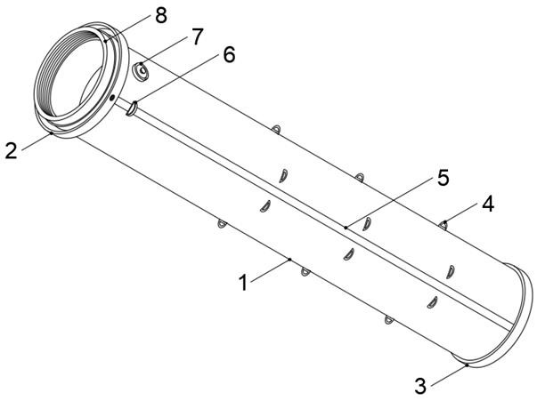
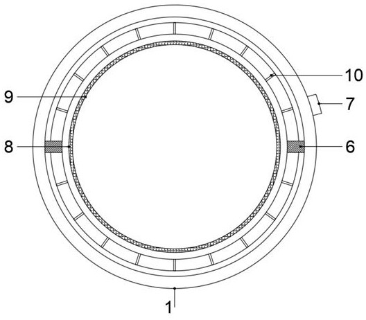
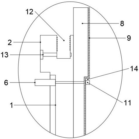
[0022] Example: as Figure 1-4 As shown in the figure, the present invention is an automatic pouring lower reinforcement device, which includes a feeding pipe body 1, a connecting ring 2 is installed at one end of the feeding pipe body 1, a bolt hole 13 is formed through the outer wall of the connecting ring 2, and a top end of the connecting ring 2 is provided with a connecting ring 2. Thread groove 12, a water inlet valve 7 is installed on the side of the outer wall of the feeding pipe body 1 close to the connecting ring 2, a chute 5 is longitudinally opened on the outer wall of the feeding pipe body 1, and a sliding block 6 is installed in the chute 5, and the lower The other end of the material pipe body 1 is provided with a discharge port 15, a reinforcing ring 3 is installed on the surface of the discharge port 15, a rubber ring 16 is sleeved on the surface of the reinforcing ring 3, and a ring is installed on the side of the outer wall of the feeding pipe body 1 close to...


PUM


Abstract

The device comprises a discharging pipe body, a connecting ring is installed at one end of the discharging pipe body, a bolt hole is formed in the outer wall of the connecting ring in a penetrating mode, a threaded groove is formed in the top end of the connecting ring, a water inlet valve is installed on the side, close to the connecting ring, of the outer wall of the discharging pipe body, and a sliding groove is longitudinally formed in the outer wall of the discharging pipe body; a sliding block is installed in the sliding groove in a clamped mode, and a discharging port is formed in the other end of the discharging pipe body. According to the automatic pouring and steel bar discharging device, the structural strength of the feeding port of the discharging pipe body is improved, dismounting and mounting of the discharging pipe body and automatic pouring equipment are facilitated, overhaul and maintenance are facilitated, adhesion of concrete grout is prevented, and it is avoided that thick concrete grout becomes lump, accumulates and agglomerates in the pipe; clear water can be conveniently provided for viscous concrete grout in the inner pipe for dilution, later cleaning and flushing are also facilitated, the residual concrete grout is prevented from being dried up and condensed in the pipe, and the problem that a pipe body is broken due to the fact that a discharging port collides with a building mold is solved.

Description

technical field [0001] The invention relates to the technical field of automatic pouring, in particular to an automatic pouring lower reinforcement device. Background technique [0002] Concrete pouring is the process of using machines to put the mixed concrete slurry into the mold until it is plasticized. In the construction project, concrete and other materials are put into the mold to form a predetermined shape, and then the construction is carried out such as storage, leveling, tamping and compaction. In the process, the blanking mechanism is used as the end unit in the pouring machine in the implementation of this process. It is the part before entering the mold, most of which are straight tubes with simple structure. Since the concrete slurry is a highly viscous object, its During the blanking process, it is easy to form lumps and agglomerates, which makes the blanking uneven and unsustainable, and affects the pouring effect. Therefore, we have improved this and propo...

Claims


Application Information

Patent Timeline
IPC IPC(8): B28B13/02
CPCB28B13/0215
Inventor 卢运才李浩
Owner 卢运才
Why Eureka
Try Eureka