
Garden ground sweeper

A technology for sweepers and gardens, which is applied in road cleaning, construction, cleaning methods, etc., can solve the problems of large suction sweepers with complex structure, large garbage storage, and high cleaning efficiency, and achieves cleaning without omission and garbage storage. Large and efficient cleaning effect

Inactive Publication Date: 2018-11-13
苏州昕润环保科技有限公司
View PDF0 Cites 3 Cited by
  • Summary
  • Abstract
  • Description
  • Claims
  • Application Information

AI Technical Summary

Problems solved by technology

[0005] The embodiment of the present application provides a garden sweeper, which is used to solve the problem of complex structure, high energy consumption and high maintenance cost of the large suction sweeper in the prior art, while the dustbin of the small sweeper is too small to be suitable for street, street, etc. The technical problems of cleaning work in living quarters and other places have achieved the technical effects of simple structure, convenient operation, clean garbage cleaning, low noise, high cleaning efficiency, and large garbage storage capacity

Method used


Image

  • Garden ground sweeper
  • Garden ground sweeper
  • Garden ground sweeper

Examples


Embodiment 1

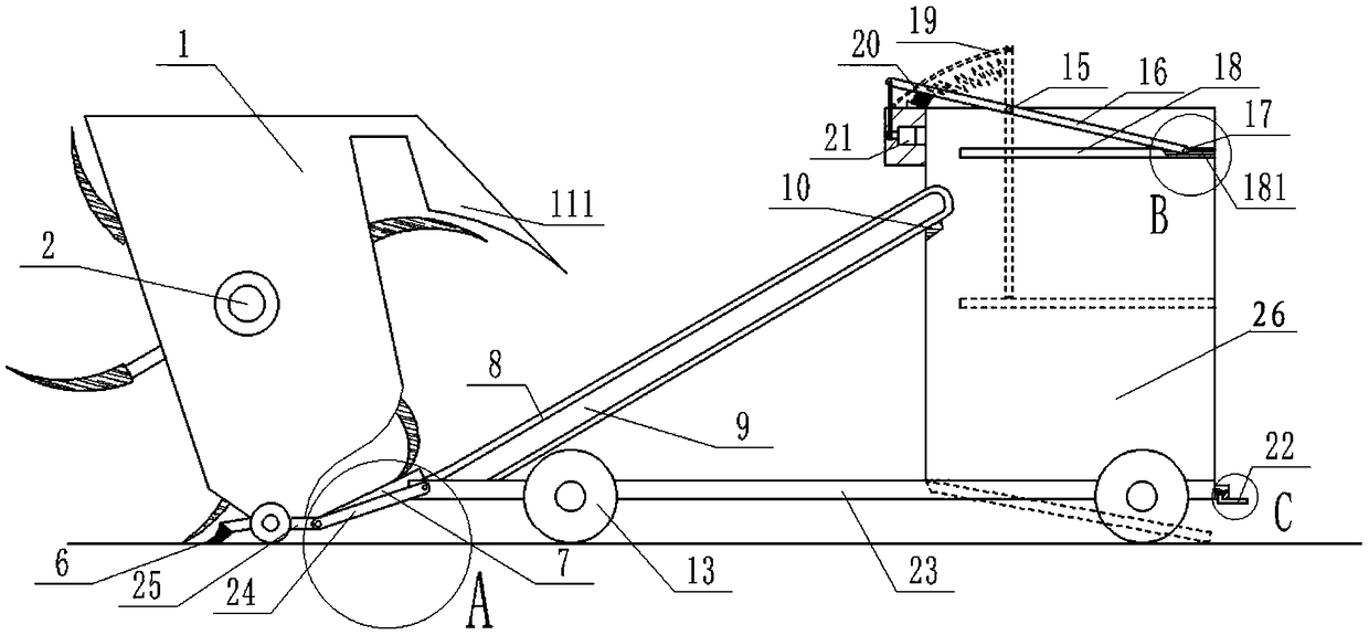
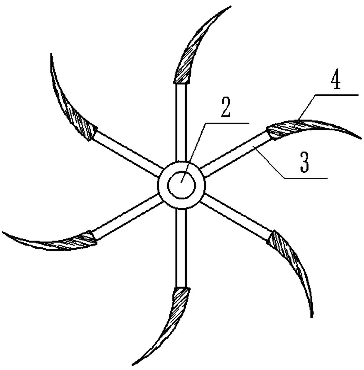
[0045] The embodiment of this application provides a garden sweeper, please refer to Figure 1 to Figure 6 , the sweeper includes:

[0046] A base 23, the two sides of the base 23 are provided with wheels 13;

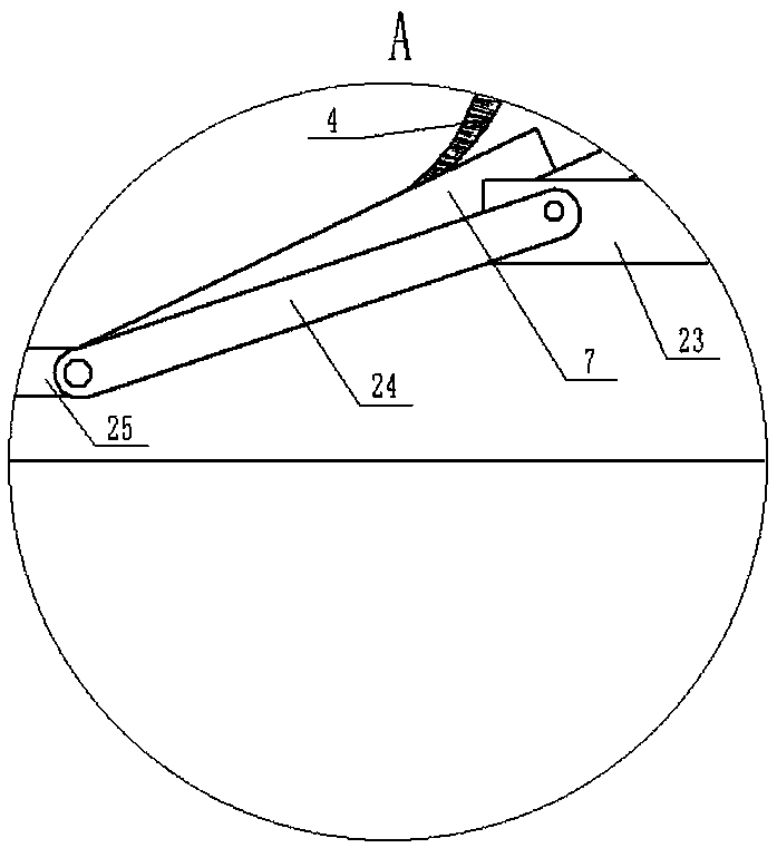
[0047] Further, the base 23 also includes: a wheel motor 14, the wheel motor 14 is pivotally connected to the wheel 13; a connecting plate 24, one end of the connecting plate 24 is fixedly connected to the base 23; a receiving seat 25, One end of the receiving seat 25 is fixedly connected with the other end of the connecting plate 24, and the bottom of the other end of the receiving seat 25 is provided with a sponge 6; the middle part of the receiving seat 25 is connected with the universal wheel shaft.

[0048] Specifically, the base 23 is a steel rectangular base with high hardness and strong ability to withstand garden garbage, and the rectangular base 23 is suitable for driving on the road; the front and rear sides of the base 23 are respectively provided with 4 s...

Embodiment 2

[0063] The embodiment of this application provides a working method of a garden sweeper, please refer to Figure 1 to Figure 6 , the specific working method is:

[0064] When it is necessary to clean up the garden garbage, start the cleaning motor 5 to drive the rotating rod 3 to rotate, so that the garbage is attached to the hair bundle 4, and the beating plate 111 beats the hair bundle 4, The garbage on the hair cluster 4 is patted and guided to the conveyor belt 8, and under the action of the conveyor belt motor 11, the garbage is transported to the second container of the second box 26 through the conveyor belt 8. placed in the space. When the wheel motor 14 on the left starts and the wheel motor 14 on the right stops, the sweeping vehicle can turn right. When the wheel motor 14 on the right starts and the wheel motor 14 on the left stops, the sweeping vehicle A left turn is possible. When enough garbage is dumped, start the moving rod motor 21 to rotate forward, so tha...


PUM


Abstract

The invention discloses a garden ground sweeper. The garden ground sweeper comprises a base, a first box, a hair collecting beam, a conveyor belt and a second box. Wheels are arranged on the two sidesof the base. The first box is arranged on the base and internally provided with a first accommodating space. The hair collecting beam is arranged in the first accommodating space and is in shaft connection with the side wall of the first accommodating space, and the rotating direction of the hair collecting beam and the motion direction of the ground sweeper are in the same plane. One end of theconveyor belt is connected with the base and is close to the position below the hair collecting beam. The second box is arranged at the end, away from the first box, of the base and internally provided with a second accommodating space. An inlet of the second accommodating space is connected with the other end of the conveyor belt. The garden ground sweeper realizes the technical effects that thestructure is simple, operation is convenient, garbage is swept and not missed, noise is small, the sweeping efficiency is high, and the garbage storage amount is large.

Description

technical field [0001] The application relates to the technical field of sanitation equipment, in particular to a garden sweeper. Background technique [0002] With the development of urbanization, the number of streets has also increased, and the workload of sanitation is increasing. It is obviously unrealistic to rely solely on manual cleaning, which is time-consuming and laborious. [0003] However, in the process of implementing the technical solutions in the embodiments of the present application, the applicant of the present application found that the above-mentioned prior art has at least the following technical problems: [0004] In the prior art, large-scale suction sweepers have complex structures, high energy consumption, and high maintenance costs, while small-scale sweepers have too small garbage bins, which are technically incapable of cleaning streets, living quarters, and other places. Contents of the invention [0005] The embodiment of the present applic...

Claims


Application Information

Patent Timeline
IPC IPC(8): E01H1/04
CPCE01H1/045E01H1/047
Inventor 黄家旺蔡海东
Owner 苏州昕润环保科技有限公司
Learn More