Reinforcement testing and optimizing method based on compaction effect

An optimization method and compaction pile technology, which can be applied in field foundation soil survey, foundation structure engineering, construction, etc., can solve the problems of non-growth, etc., and achieve small disturbance of pile body, no influence of pile body density, and fast measurement time Effect

Active Publication Date: 2018-11-13
EAST CHINA JIAOTONG UNIVERSITY
View PDF3 Cites 3 Cited by
  • Summary
  • Abstract
  • Description
  • Claims
  • Application Information

AI Technical Summary

Problems solved by technology

[0018] The purpose of the present invention is to provide a kind of reinforcement test and optimization method based on the compaction effect, measure the stable compaction force around the pile and the compaction force at the bottom of the pile through the earth pressure cell, and solve the problem of how to measure the compaction effect of the rammer; The relationship between compaction force, soil compaction coefficient, and tamping energy, and a method to optimize the shape of the rammer and the number of tamping times are proposed, and the problem of which shape tamping tool can obtain the best tamping effect at the minimum compaction energy is solved. Problem: The relationship between the compaction coefficient of the pile body and the micro-penetrator was established, and a method for measuring the compaction coefficient of the pile body by the penetration resistance was proposed, which reduced the disturbance to the ramming pile and at the same time reduced the impact caused by the ramming process. The energy loss caused by the ring knife method pit; according to the principle of the minimum compaction energy and the principle that the number of tamping times exceeds a certain number of times and basically does not increase, a combination suitable for the optimization of the existing railway is proposed

Method used


Image

  • Reinforcement testing and optimizing method based on compaction effect
  • Reinforcement testing and optimizing method based on compaction effect
  • Reinforcement testing and optimizing method based on compaction effect

Examples


Embodiment Construction

[0080] Embodiments of the present invention will now be described with reference to the drawings, in which like reference numerals represent like elements.

[0081] Please refer to Figure 1-9 , the described reinforcement test and optimization method based on the compaction effect includes the following steps:

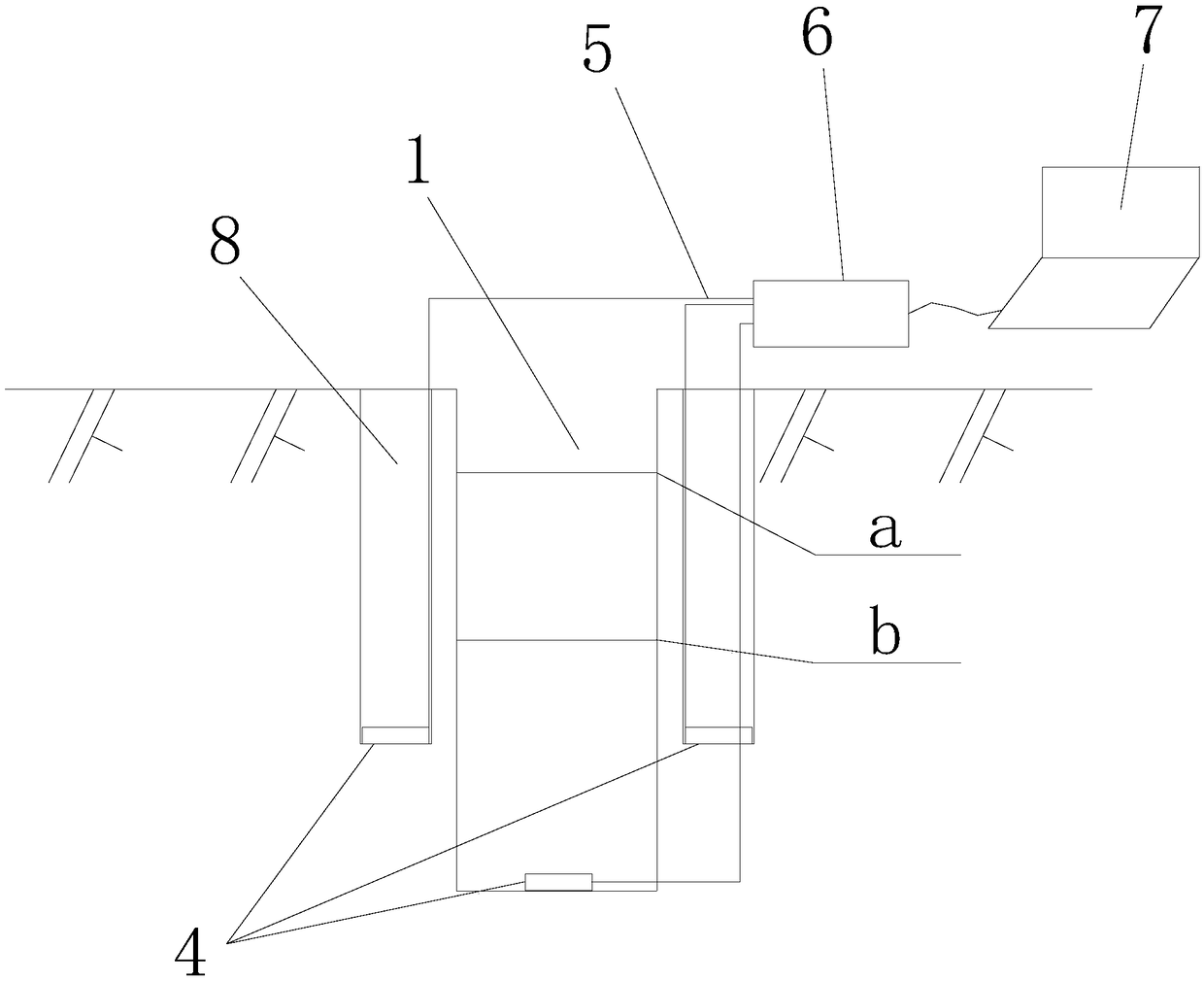
[0082] 1. Test model design

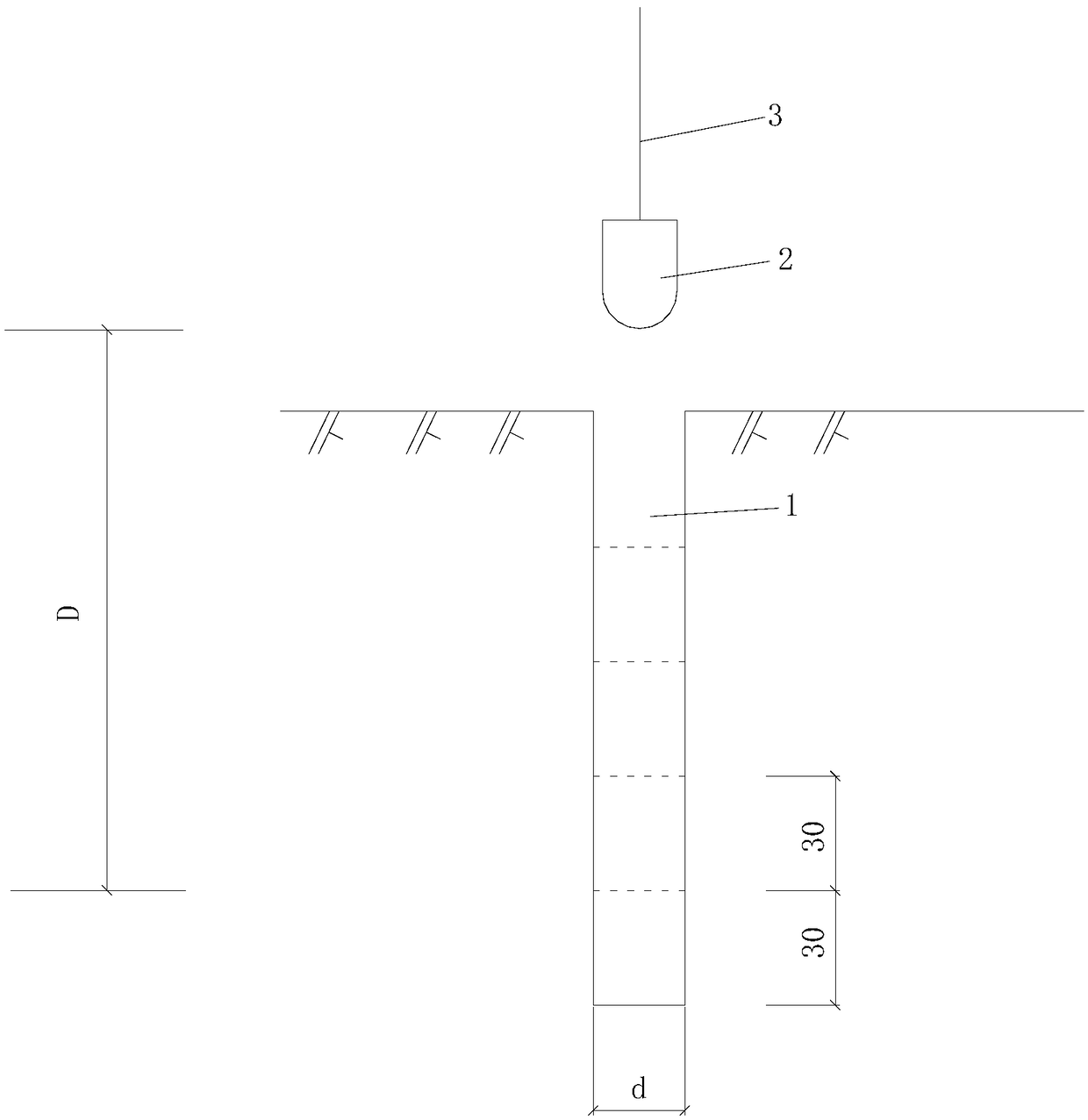
[0083] In the reinforcement of existing railways, the soil-cement compaction pile relies on drilling a hole in the existing railway subgrade, filling the hole with a mixture of cement and plain soil, and using a rammer to compact it into a soil-cement compaction pile. The pile is compacted under the action of the rammer, and at the same time, the original soil around the pile is compacted to both sides, so that the bearing capacity of the soil around the pile is improved, and the compaction coefficient of the pile body is also increased to increase the bearing capacity of the pile.

[0084] The present invention proposes to use the comp...


PUM


Abstract

The invention discloses a reinforcement testing and optimizing method based on a compaction effect. The method optimizes the shape of a pounder and the pounding times through drilling, arrangement ofsoil pressure boxes into drilled holes and pounding of soil in the drilled holes by using the pounder. The pile periphery stable compaction force and the pile bottom compaction force are measured through the soil pressure boxes to solve the problem how to measure the compaction effect of the pounder; through the relation among the compaction force, the soil compaction coefficients and the poundingenergy, a method for optimizing the shape of the pounder, the pounding times and the drop distance of the pounder is provided to solve the problem which compaction tool can obtain optimal compactioneffect under the lowest compaction energy; and the relation between pile body compaction coefficients and a micro inserter is built, and a method for measuring the pile body compaction coefficients byinsertion resistance is provided, so that the disturbance on pounding piles is reduced, and the energy loss in the pounding process is reduced. Based on the principle of basically not increasing thecompaction force when the compaction energy is the lowest and the pounding times do not exceed one time, an optimal combination suitable for existing railway is provided.

Description

technical field [0001] The invention relates to the technical field of construction, in particular to a reinforcement test and optimization method based on compaction effect. Background technique [0002] At present, many existing railways in China cannot meet the needs of the surge of passengers and freight, and need to be upgraded to speed up. However, the bearing capacity of the existing railway subgrade may be insufficient. At present, cement-soil compaction piles are often used for subgrade reinforcement. Cement-soil compaction pile reinforcement is a method of mechanically forming holes in the existing railway foundation bed, the diameter of which is slightly smaller than the distance between sleepers, and then layering and compacting a mixture of cement and plain soil in the holes. After the reinforcement is completed, the mixture of cement and plain soil solidifies into a cement-soil pile with good uniformity and high strength. At the same time, during the compaction...

Claims


Application Information

Patent Timeline
Patent Type & Authority Applications(China)
IPC IPC(8): E02D1/02
CPCE02D1/022
Inventor 赵秀绍李凯徐长节耿大新石钰锋莫林利谭周勇邹远航
Owner EAST CHINA JIAOTONG UNIVERSITY
Why Eureka
Try Eureka