
Automatic drainage joint

An automatic drainage and water outlet technology, applied in the direction of engine components, valve details, diaphragm valves, etc., can solve problems such as faucet freezing, achieve the effect of preventing faucet from freezing, enriching functions, and preventing water pipes from freezing

Active Publication Date: 2018-11-13
张杰
View PDF9 Cites 0 Cited by
  • Summary
  • Abstract
  • Description
  • Claims
  • Application Information

AI Technical Summary

Problems solved by technology

[0004] However, in addition to the water pipe, there is also residual water in the faucet. Although the water in the water pipe can be automatically discharged by using the above-mentioned automatic drain valve, the automatic drain valve will not be removed after it is connected to the faucet. The remaining water in the interior cannot be discharged through the automatic drain valve, so there is a problem that the faucet is frozen

Method used


Image

  • Automatic drainage joint
  • Automatic drainage joint
  • Automatic drainage joint

Examples


Embodiment 1

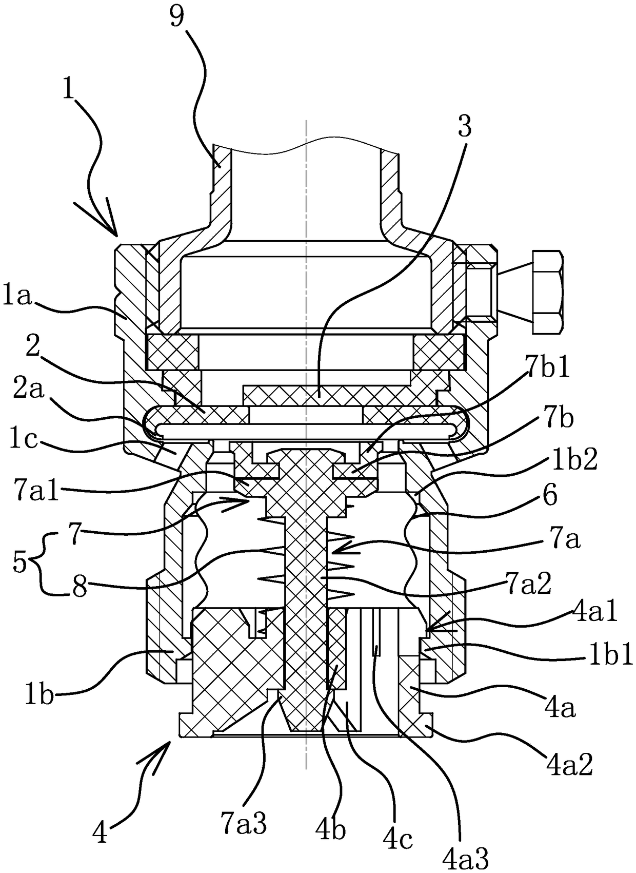
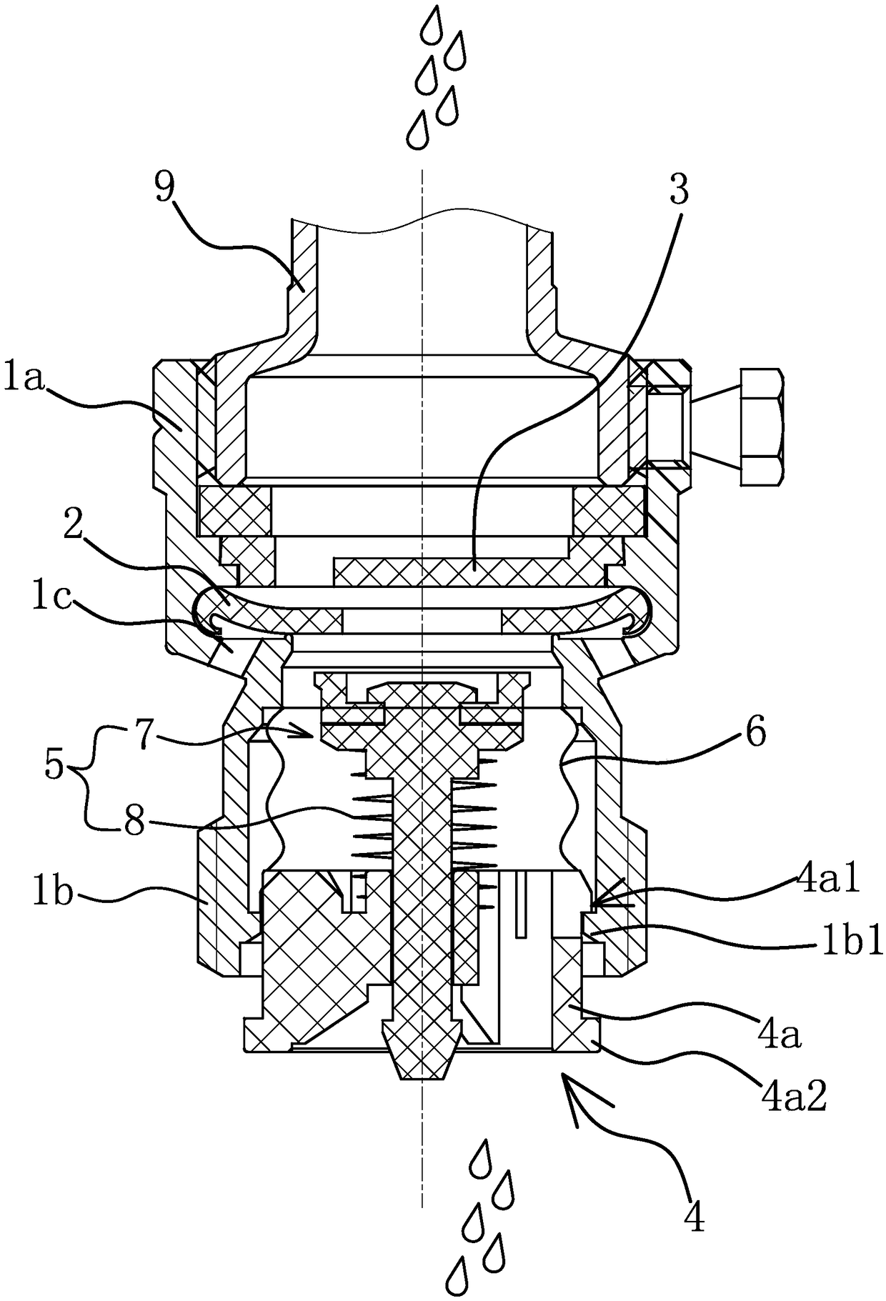
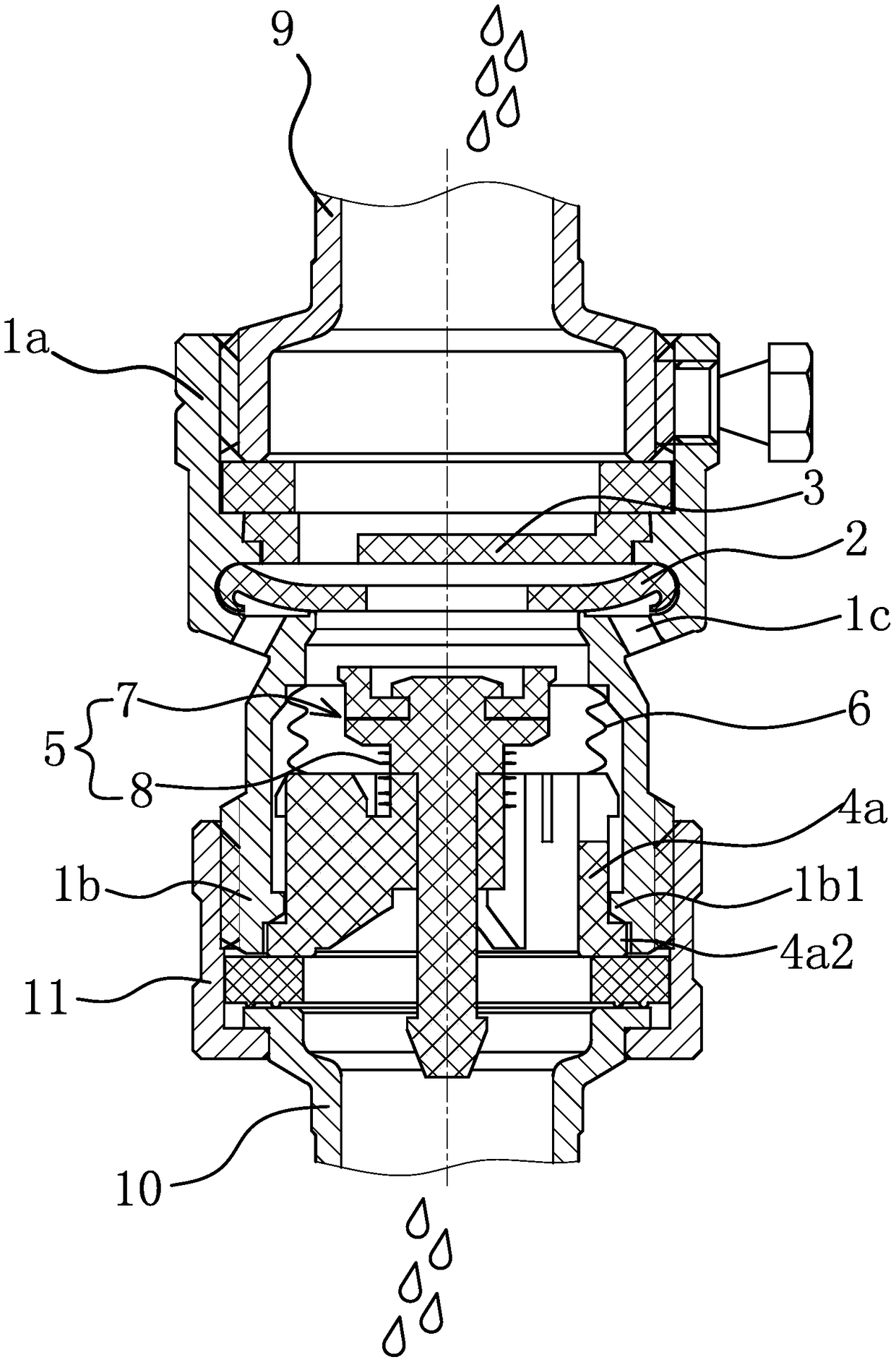
[0038] Such as figure 1 , figure 2 , image 3 and Figure 4 As shown, an automatic drainage joint includes a body 1. The upper end of the body 1 is a water inlet 1a for connecting with a faucet 9. A locking hole is provided through the outer side of the water inlet 1a, and the inner thread of the locking hole is connected with a locking hole. Screw, when installing, put the water inlet 1a of the body 1 outside the water outlet of the water tap 9, then tighten the locking screw to fix the body 1 on the water outlet of the water tap 9. The lower end of the main body 1 is the water outlet 1b used to connect with the water pipe 10, and the outside of the water outlet 1b has threads. When in use, the lock nut 11 is inserted outside the end of the water pipe 10, and the end of the water pipe 10 is offset against the end surface of the water outlet 1b. Rely on, and then screw the lock nut 11 on the thread on the outside of the water outlet 1b, so that the water pipe 10 and the bo...

Embodiment 2

[0051] The structure and principle of this embodiment are basically the same as that of Embodiment 1, the difference is that in this embodiment, the support member 5 is a support spring, the lower end of the support spring is inserted on the guide column 4b, and the lower end surface of the support spring is against the on the upper end surface of each connecting piece 4c. The support member 5 is a support spring, the existence of each connecting piece 4c makes the setting of the ferrule 4 not affect the normal water outlet, and the setting of the guide post 4b enables the support spring to be inserted on the guide post 4b to form a connection with the ferrule 4, Therefore, the matching relationship between the support member 5 and the gasket 2 can be changed by changing the position of the ferrule 4, so that the automatic drainage joint can automatically discharge the residual water in the water pipe 10 when the water pipe 10 is connected to prevent the water pipe from 10 fre...


PUM


Abstract

The invention provides an automatic drainage joint, belongs to the technical field of machinery and solves the problem that an existing automatic drainage joint does not have a function of preventinga faucet from being frozen. The automatic drainage joint comprises a body, the upper end of which is the water inlet end and the lower end of which is the water outlet end. An annular sealing pad anda separation blade, the cross section of which is smaller than that of the sealing pad, are arranged in the water inlet end; the separation blade leans against the sealing pad and closes a pore in a center hole of the sealing pad; an air inlet hole communicating to the water outlet is formed in the outer side of the body; when water flows inward, the sealing pad can deform downward and close the air inlet hole, a cutting ferrule is slidably connected in the water outlet end, the cutting ferrule is connected to an elastic supporting part, a gap is formed between the upper end of the supportingpart and the lower end surface of the sealing pad, and after the cutting ferrule moves upward, the upper end of the supporting part can lean against the sealing pad. The automatic drainage joint provided by the invention has the advantages of preventing the faucet from being frozen and preventing a water pipe from being frozen.

Description

technical field [0001] The invention belongs to the technical field of machinery and relates to a joint, in particular to an automatic drainage joint. Background technique [0002] With the continuous development of society, people have higher and higher requirements for their own living environment, and more and more houses (especially in some developed countries) have their own gardens, so that people can plant flowers and vegetables in the gardens. To plant flowers and vegetables, it is necessary to install a faucet in the garden and connect a water pipe for use, so that it is convenient for people to sprinkle water in a large area. When the faucet is closed, there will often be a lot of water remaining in the water pipe. In this case, in winter when the temperature is low or in some areas where the weather is cold all the year round, it is easy to cause the water pipe to freeze due to the residual water and make it unusable. In severe cases, it may Water pipes may also ...

Claims


Application Information

Patent Timeline
Patent Type & Authority Applications(China)
IPC IPC(8): F16K7/12F16K31/12
CPCF16K7/12F16K31/12
Inventor 张杰
Owner 张杰
Learn More