
Shock-absorbing installation base for textile machine

A technology for installing bases and textile machines, applied in the direction of springs/shock absorbers, supporting machines, mechanical equipment, etc., can solve the problems of textile quality reduction, user economic loss, poor shock absorption effect, etc., and achieve increased textile accuracy , Increase practicality, increase the effect of maneuverability

Inactive Publication Date: 2018-11-13
芜湖瀚德信息科技有限公司
View PDF0 Cites 7 Cited by
  • Summary
  • Abstract
  • Description
  • Claims
  • Application Information

AI Technical Summary

Problems solved by technology

[0002] Textile machine, also known as textile machine, loom, cotton spinning machine, etc., textile machine is the full name of a tool that processes raw materials such as thread, silk, and hemp into silk thread and then weaves it into cloth, such as spinning pendant, spinning wheel, spindle, and pedal loom. There are also mechanical looms, numerical control automatic looms, etc., when weaving in textile factories, we need to use textile machines. Most of the existing textile machines are fixed on the base. , the shock absorption effect is poor, and the vibration generated when the textile machine is working will inevitably have a certain impact on the textile precision of the textile machine, resulting in a reduction in the quality of the textile, bringing losses to the user's economy, and reducing the practicality of the textile machine. sex

Method used


Image

  • Shock-absorbing installation base for textile machine

Examples


Embodiment Construction

[0018] The following will clearly and completely describe the technical solutions in the embodiments of the present invention with reference to the accompanying drawings in the embodiments of the present invention. Obviously, the described embodiments are only some, not all, embodiments of the present invention. All other embodiments obtained by persons of ordinary skill in the art based on the embodiments of the present invention belong to the protection scope of the present invention.

[0019] According to an embodiment of the present invention, a shock-absorbing mounting base for a textile machine is provided.

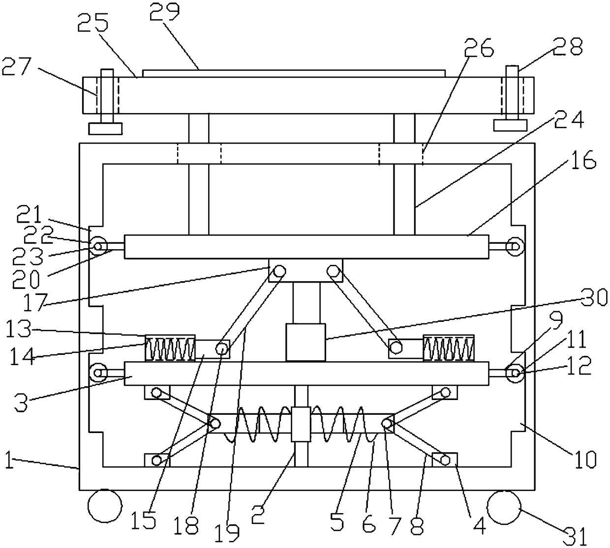
[0020] Such as figure 1 As shown, a shock-absorbing installation base for a textile machine according to an embodiment of the present invention includes a housing 1, a telescopic rod-2 is provided in the middle of the inner bottom of the housing 1, and a support is provided at the top of the telescopic rod-2. Plate one 3, both sides of the bottom end of the support...


PUM


Abstract

The invention discloses a shock-absorbing installation base for a textile machine. The shock-absorbing installation base comprises a shell, wherein a first telescopic rod is arranged at the middle ofthe bottom end inside the shell, a first supporting plate is arranged at the top end of the first telescopic rod, and the two sides of the bottom end of the first supporting plate and the two sides ofthe bottom end inside the shell are each provided with a first fixed block; second telescopic rods are symmetrically arranged on the two sides of the first telescopic rod, a second spring is arrangedoutside each second telescopic rod, the middle of each first fixed block and the side, far away from the first telescopic rod, of each corresponding second telescopic rod are each provided with a first connecting shaft, and the first connecting shaft on each first fixed block is connected with the first connecting shaft on the corresponding second telescopic rod through a first fixing rod; firstconnecting rods are symmetrically arranged on the two sides of the first supporting plate, one side of each first connecting rod is far away from the first supporting plate, the two inner walls of theshell are each provided with a first sliding groove, a first sliding wheel is arranged in each first sliding groove, and each first sliding wheel is connected with the corresponding first connectingrod through a first rotating shaft; and sleeving rods are symmetrically arranged on the two sides of the top end of the first supporting plate, a first spring is arranged in each sleeving rod, and theopposite sides of the two sleeving rods are each provided with a supporting rod.

Description

technical field [0001] The invention relates to the technical field of textiles, in particular to a shock-absorbing installation base for a textile machine. Background technique [0002] Textile machine, also known as textile machine, loom, cotton spinning machine, etc., textile machine is the full name of a tool that processes raw materials such as thread, silk, and hemp into silk thread and then weaves it into cloth, such as spinning pendant, spinning wheel, spindle, and pedal loom. There are also mechanical looms, numerical control automatic looms, etc., when weaving in textile factories, we need to use textile machines. Most of the existing textile machines are fixed on the base. , the shock absorption effect is poor, and the vibration generated when the textile machine is working will inevitably have a certain impact on the textile precision of the textile machine, resulting in a reduction in the quality of the textile, bringing losses to the user's economy, and reducin...

Claims


Application Information

Patent Timeline
IPC IPC(8): F16M3/00F16F15/04F16F15/023
CPCF16M3/00F16F15/023F16F15/04
Inventor 程瀚
Owner 芜湖瀚德信息科技有限公司
Learn More