
Heat source heat dissipation device

A heat dissipation device and heat source technology, applied in cooling/heating devices of lighting devices, lighting devices, semiconductor devices of light-emitting elements, etc., can solve the problems of effective heat dissipation and difficult heat source, and achieve the effect of solving heat dissipation problems

Pending Publication Date: 2018-11-13
INST OF ENGINEERING THERMOPHYSICS - CHINESE ACAD OF SCI
View PDF9 Cites 7 Cited by
  • Summary
  • Abstract
  • Description
  • Claims
  • Application Information

AI Technical Summary

Problems solved by technology

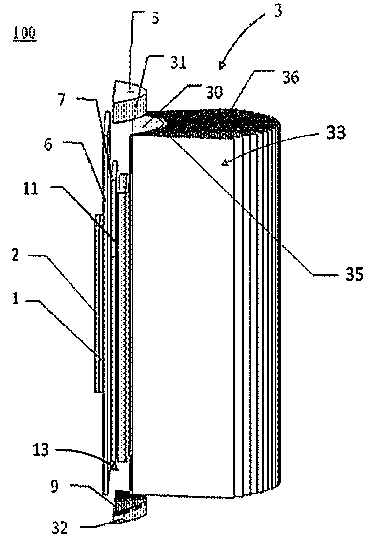
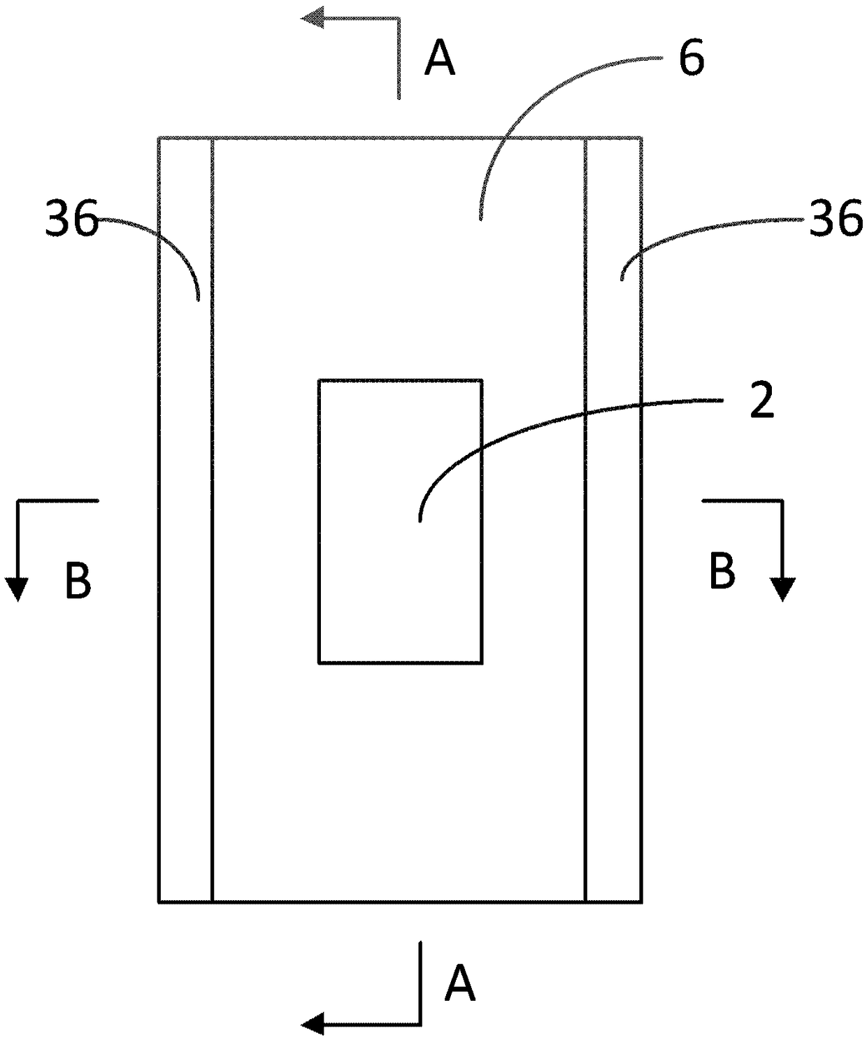
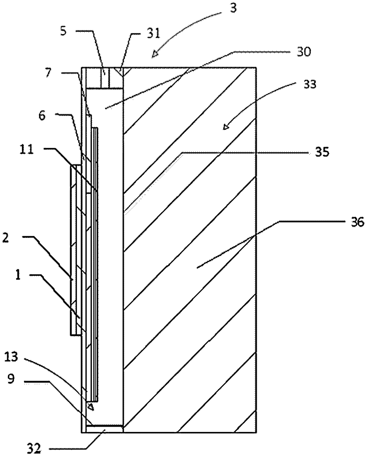
[0004] The present invention aims to provide a heat dissipation device for a heat source, especially a side-emitting LED lamp, to solve the problem that it is difficult to effectively dissipate heat through liquid phase change when the heat source is at least partially inclined

Method used


Image

  • Heat source heat dissipation device
  • Heat source heat dissipation device
  • Heat source heat dissipation device

Examples


Embodiment Construction

[0030] In order to make the purpose, technical solutions and advantages of the embodiments of the present invention clearer, the technical solutions in the embodiments of the present invention will be clearly and completely described below in conjunction with the drawings in the embodiments of the present invention. Obviously, the described embodiments It is a part of embodiments of the present invention, but not all embodiments. Based on the embodiments of the present invention, all other embodiments obtained by persons of ordinary skill in the art without making creative efforts belong to the protection scope of the present invention. In addition, the drawings are only schematic representations of embodiments of the invention and are not necessarily drawn to scale.

[0031] Unless otherwise defined, the technical terms or scientific terms used in the present invention shall have the usual meanings understood by those skilled in the art to which the present invention belongs....


PUM


Abstract

The invention provides a heat source heat dissipation device. A heat source is a platy heat source. At least part of the heat source is inclined relative to the horizontal plane. The heat dissipationdevice comprises a heat conduction plate, a heat dissipation assembly and a platy porous medium liquid absorption core, wherein the heat conducting plate is arranged on one side of the platy heat source to make heat transfer contact with the platy heat source; the heat dissipation assembly is arranged on the side, opposite to the heat source, of the heat conduction plate and connected to the periphery of the heat conduction plate to define a closed steam cavity with the heat conduction plate; the steam cavity is suitable for storing a liquid-state phase change heat dissipation medium; the platy porous medium liquid absorption core is located in the steam cavity and makes heat transfer contact with the heat conduction plate; the porous medium liquid absorption core is suitable for absorbingthe liquid-state phase change heat dissipation medium to enable the liquid-state phase change heat dissipation medium absorbing heat to be converted into gas to get into the steam cavity and be condensed into a liquid state in the steam cavity through the heat dissipation assembly again so as to be reabsorbed by the porous medium liquid absorption core.

Description

technical field [0001] The invention relates to the field of heat dissipation, in particular to a heat dissipation device for a heat source. Background technique [0002] Light-emitting sources, such as LED lamps, most of their input power will be converted into heat, and the accumulation of heat will cause the temperature of the light-emitting source to rise, causing the spectral line drift of the light-emitting source, reducing the luminous efficiency, and shortening the life. Therefore, the heat dissipation device is a key component in the design of high-power light sources such as LED lamps. Common profile heat dissipation and heat pipes have limited heat dissipation capabilities, and it is difficult to produce a good heat dissipation effect on high-power light sources. Liquid phase change heat dissipation has become the mainstream technology to solve the heat dissipation of high-power light sources. [0003] Liquid phase change heat dissipation has been used to solve ...

Claims


Application Information

Patent Timeline
IPC IPC(8): F28D15/04F28F21/08F21V29/51F21V29/89F21Y115/10
CPCF21V29/51F21V29/89F28D15/046F28F21/081F21Y2115/10
Inventor 张桂英胡学功
Owner INST OF ENGINEERING THERMOPHYSICS - CHINESE ACAD OF SCI
Learn More