Power cyclic test method and system for semiconductor devices

A power cycle and test method technology, applied in the direction of single semiconductor device test, semiconductor working life test, etc., can solve the problems that affect the reliability of power cycle test equipment, low measurement efficiency, and affect the reliability of DC power supply, etc.

Active Publication Date: 2018-11-13
NORTH CHINA ELECTRIC POWER UNIV (BAODING)
View PDF14 Cites 14 Cited by
  • Summary
  • Abstract
  • Description
  • Claims
  • Application Information

AI Technical Summary

Problems solved by technology

[0004] The current power cycle test is in the form of connecting the devices under test in series. The number of series connection is limited by the voltage of the DC power supply, and the measurement efficiency is low.
At the same time, the DC power supply also undergoes repeated switching actions with the power cycle test. T

Method used


Image

  • Power cyclic test method and system for semiconductor devices
  • Power cyclic test method and system for semiconductor devices
  • Power cyclic test method and system for semiconductor devices

Examples


Embodiment 1

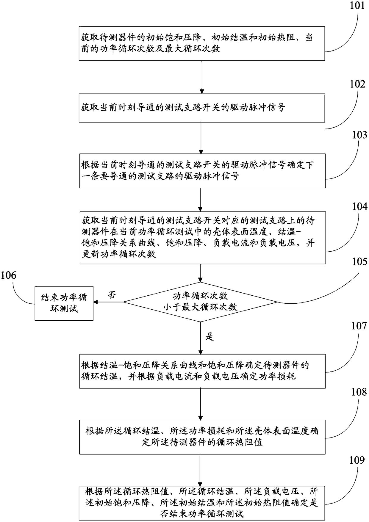
[0078] figure 2 It is a flowchart of a power cycle testing method for a semiconductor device provided in Embodiment 1 of the present invention. Such as figure 2 As shown, the power cycle test method of the semiconductor device is applied to a power cycle test device, and the power cycle test device includes a plurality of test branches connected in parallel, a DC power supply and a water cooler, and each test branch includes: A test branch switch, a number of devices under test connected in series with the test branch switch, and each of the devices under test is connected in series, each of the test branches is connected to the DC power supply to form a closed loop, and each The test branch switch is only turned on once in a power cycle test cycle, the DC power supply is used to provide a constant load current for the test branch, the water cooler is set corresponding to the test branch, and the water cooler is used To cool each of the devices under test; the power cycle ...

Embodiment 2

[0128] Figure 7 A structural block diagram of a power cycle testing system for a semiconductor device provided in Embodiment 2 of the present invention. Such as Figure 7 As shown, the power cycle test system of semiconductor devices, the power cycle test system is applied to the power cycle test device, the power cycle test device includes a plurality of test branches connected in parallel, DC power supply and water cooler, each of the The test branch includes: a test branch switch, a number of devices under test connected in series with the test branch switch, and each of the test devices is connected in series, each of the test branches is connected to the DC power supply to form a closed circuit, and each test branch switch is only turned on once in a power cycle test period, the DC power supply is used to provide a constant load current for the test branch, and the water cooler is set corresponding to the test branch , the water cooler is used to cool each of the devic...


PUM


Abstract

The invention discloses a power cyclic test method and system for semiconductor devices, comprising a plurality of test branches connected in parallel and a power cyclic test device. A drive pulse signal of one next test branch to be made can be determined according to a drive pulse signal of a switch of the test branch that is made at current moment; the multiple test branches can be subjected toalternate cyclic heating and cooling; heating time for one test branch is utilized to heat other test branches; the efficiency of power cyclic test is greatly improved; it can also be ensured that switches of the test branches are closed in alternate cyclic manner; therefore, a direct-current power supply can output constant direct current continuously, the aging issue of the direct-current powersupply due to repeating of switching on and off is avoided, long-term operational reliability of the direct-current power supply is improved, and reliability of the power cyclic test device is further improved.

Description

technical field [0001] The invention relates to the field of semiconductor device reliability testing, in particular to a power cycle testing method and testing system for semiconductor devices. Background technique [0002] Power semiconductor devices are more and more widely used in power systems. Currently, at least 60% of the world's electric energy is controlled by them. In the future, under the trend of global energy Internet, with large-scale new energy generation connected to the grid and electric vehicles This proportion will increase significantly when mobile unpredictable loads are connected to the grid. Therefore, research work on power semiconductor devices has also become a hot spot in recent years, especially high-voltage and high-power semiconductor devices. At present, the high-voltage and high-power semiconductor devices used in flexible direct current transmission systems are mainly IGBT devices. At the same time, there are two different packaging forms f...

Claims


Application Information

Patent Timeline
IPC IPC(8): G01R31/26
CPCG01R31/2642
Inventor 邓二平赵雨山郭楠伟赵志斌黄永章
Owner NORTH CHINA ELECTRIC POWER UNIV (BAODING)
Why Eureka
Try Eureka