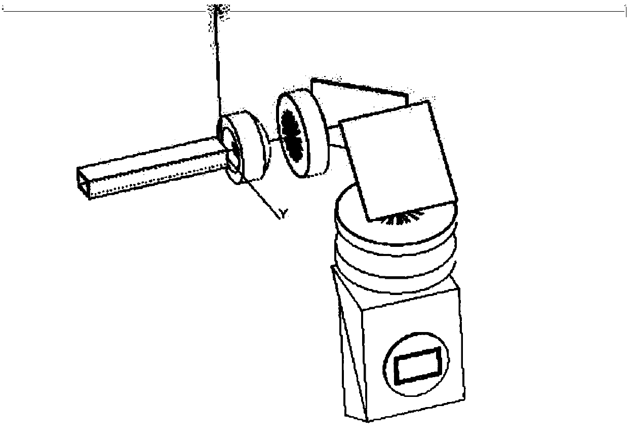
Lighting assembly applied in laser projection device

A technology of lighting components and laser projection, applied in the field of projection, can solve the problems of high cost and large volume of lighting components

Inactive Publication Date: 2018-11-13
QINGDAO HISENSE LASER DISPLAY CO LTD
View PDF5 Cites 6 Cited by
  • Summary
  • Abstract
  • Description
  • Claims
  • Application Information

AI Technical Summary

Problems solved by technology

[0005] The object of the present invention is to provide a lighting assembly used in a laser projection device, so as to solve the defects of large volume and high cost of the lighting assembly in the laser projection device proposed in the background art

Method used


Image

  • Lighting assembly applied in laser projection device
  • Lighting assembly applied in laser projection device
  • Lighting assembly applied in laser projection device

Examples


Embodiment Construction

[0036] The following will clearly and completely describe the technical solutions in the embodiments of the present invention with reference to the accompanying drawings in the embodiments of the present invention. Obviously, the described embodiments are only part of the embodiments of the present invention, not all of them. Based on the embodiments of the present invention, all other embodiments obtained by persons of ordinary skill in the art without making creative efforts belong to the protection scope of the present invention.

[0037] It should be noted that all directional indications (such as up, down, left, right, front, back...) in the embodiments of the present invention are only used to explain the relationship between the components in a certain posture (as shown in the accompanying drawings). Relative positional relationship, movement conditions, etc., if the specific posture changes, the directional indication will also change accordingly.

[0038] In addition,...


PUM


Abstract

The invention provides a lighting assembly applied in a laser projection device. The lighting assembly includes a first spherical lens, a second spherical lens, and an aspherical lens, wherein the first spherical lens is located on a path of a first outgoing light beam emitted from a photoconductive tube for increasing the deflection angle of the first outgoing light beam and performing field curvature correction and distortion correction on the first outgoing light beam; the second spherical lens is located on a path of a second outgoing light beam emitted from the first spherical lens for performing field curvature correction and distortion correction on the second outgoing light beam; and the aspheric lens is located on a path of a third outgoing light beam emitted from the second spherical lens for performing aberration correction on the third outgoing light beam and projecting the third outgoing light beam to a TIR (Total Internal Reflection) prism, so as to enable the TIR prism to totally reflect the third outgoing light beam to a DMD module. The scheme of the lighting assembly applied in a laser projection device reduces the lateral dimension and the longitudinal height of the lighting assembly by reducing the number of lenses and using special lenses, and also reduces the overall cost at the same time, so as to solve the problem that the lighting assembly is large in the volume and high in the cost on the premise of guaranteeing that the performance of the laser projection device is not affected.

Description

technical field [0001] The invention relates to the field of projection technology, in particular to an illumination assembly applied to a laser projection device. Background technique [0002] A laser projection device is a device that can project images or videos onto a screen and is widely used in homes, offices, schools and entertainment venues. As an emerging projection display technology, laser projection products have higher brightness and lifespan than LED projection products. However, at present, laser projectors generally have the problems of large size and high price, which seriously affects the development of laser cinemas. [0003] like figure 1 , 2 As shown, it is a structural schematic diagram of the lighting components in the laser projection device used in the design of the lighting system in the prior art. The prior art generally adopts the architectural mode of 4 spherical lenses, 2 flat mirrors, and TIR, that is, 4 Spherical lens + 2 flat reflectors +...

Claims


Application Information

Patent Timeline
Patent Type & Authority Applications(China)
IPC IPC(8): G03B21/20
CPCG03B21/2033G03B21/206G03B21/2066G03B21/208
Inventor 王宇
Owner QINGDAO HISENSE LASER DISPLAY CO LTD
Why Eureka
Try Eureka