
Touch screen and mobile terminal

A mobile terminal and touch screen technology, which is applied in the direction of instruments, electrical digital data processing, data processing input/output process, etc., and can solve the problems of metal lapping blocks exposed inside the visible area 17', poor appearance, small area, etc. , to achieve the effect of reducing the appearance of bad

Active Publication Date: 2018-11-13
WUHAN CHINA STAR OPTOELECTRONICS SEMICON DISPLAY TECH CO LTD
View PDF6 Cites 5 Cited by
  • Summary
  • Abstract
  • Description
  • Claims
  • Application Information

AI Technical Summary

Problems solved by technology

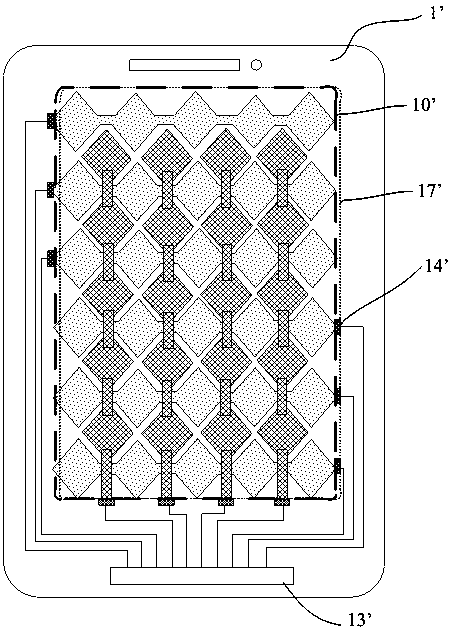
[0003] Due to the requirement of narrow frame, the visual area (Visual Area, VA) boundary 17' of the outermost layer glass (Cover Glass, CG) is usually very close to the metal pad (Pad) 14' of the touch area, for example, in some cases , there is a distance of 0.1mm~0.3mm between the two; if the outermost layer of glass is offset from the touch screen, there is a risk of exposing the metal overlapping block 14' to the inside of the visible area 17', such as figure 1 shows a situation where the two are misaligned
[0004] Since the metal bonding blocks 14' correspond to the sensing electrode channels one by one, and the area of ​​each metal bonding block 14' is relatively small, its length is usually smaller than the distance between adjacent electrode channels, if it is exposed in the visible area 17' Inside, there will be a black dotted line in the viewing angle, so there is an obvious appearance defect

Method used


Image

  • Touch screen and mobile terminal
  • Touch screen and mobile terminal
  • Touch screen and mobile terminal

Examples


Embodiment Construction

[0031] The following will clearly and completely describe the technical solutions in the embodiments of the present invention with reference to the accompanying drawings in the embodiments of the present invention. Obviously, the described embodiments are only part of the embodiments of the present invention, not all of them. Based on the embodiments of the present invention, all other embodiments obtained by persons of ordinary skill in the art without making creative efforts belong to the protection scope of the present invention.

[0032] Here, it should also be noted that, in order to avoid obscuring the present invention due to unnecessary details, only the structures and / or processing steps closely related to the solution according to the present invention are shown in the drawings, and the related Other details are not relevant to the invention.

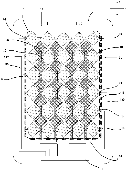
[0033] Such as figure 2 As shown, it shows a schematic structural view of the first embodiment of a touch screen provided ...


PUM


Abstract

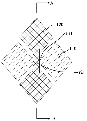
The embodiment of the invention discloses a touch screen. The touch screen comprises a touch area, multiple first conducting lines and multiple second conducting lines which are arranged in a mutuallyinsulating and overlapped mode are arranged in the touch area; each first conducting line comprises multiple first sensing electrodes which are arranged at intervals and first connection parts, eachsecond conducting line comprises multiple second sensing electrodes which are arranged at intervals and second connection bridges, and each of the first conducting lines and the second conducting lines is connected with a binding area of which a wire extends to the touch screen through a lap joint block; virtual lap joint blocks are arranged at least one end of each lap joint block at intervals, and the virtual lap joint blocks are insulated from the first sensing electrodes, the second sensing electrodes and the lap joint blocks; and on each side, with the lap joint blocks, in the touch area,the lap joint blocks and at least one virtual lap joint block jointly form a complete shielding strip capable of shielding the side on the view. The invention further discloses a corresponding mobileterminal. According to the touch screen and the mobile terminal, the appearance badness capable of being visually observed by eyes can be reduced, and the wire badness of the touch area can be detected.

Description

technical field [0001] The invention relates to the display field, in particular to a touch screen and a mobile terminal. Background technique [0002] The touch screen has many advantages such as fast response speed, accurate positioning, multi-touch support, and long service life, and is widely used in mobile terminals. In order to make users more comfortable to use, the size of the substrate of the touch screen is increased and the resolution is further improved, while the frame is required to be narrower and narrower. Such as figure 1 As shown, a schematic structural diagram of an existing touch screen is shown. figure 1 Among them, there is a touch area 10' on the touch screen 1', on both sides of the touch area 10' there are wiring areas, on the lower side is a wiring bonding area (Bonding area) 13', and on its upper side Set the camera, earpiece hole, infrared sensor hole, etc. [0003] Due to the requirement of narrow frame, the visual area (Visual Area, VA) boun...

Claims


Application Information

Patent Timeline
Patent Type & Authority Applications(China)
IPC IPC(8): G06F3/044G06F3/047
CPCG06F3/044G06F3/047G06F2203/04102G06F2203/04103
Inventor 叶剑
Owner WUHAN CHINA STAR OPTOELECTRONICS SEMICON DISPLAY TECH CO LTD
Learn More