Supercharge Your Innovation With Domain-Expert AI Agents!

Lamp driver for LED lamp and LED lamp to be arranged in fluorescent lamp

A technology of LED driver and LED lamp, which is applied in the direction of electric lamp circuit layout, light source, electric light source, etc., can solve problems such as flickering and/or flashing of LED lamps, high-efficiency LED lamp loss, etc., and achieves efficient and effective suppression and high-efficiency ripple The effect of current

Active Publication Date: 2018-11-13
LEDVANCE GMBH
View PDF12 Cites 0 Cited by
  • Summary
  • Abstract
  • Description
  • Claims
  • Application Information

AI Technical Summary

Problems solved by technology

However, LC passive loads cause undesired losses in high-efficiency LED lamps
[0007] Therefore, currently available lamp drivers do not solve the problem of flickering and / or flickering of LED lamps due to ripple

Method used


Image

  • Lamp driver for LED lamp and LED lamp to be arranged in fluorescent lamp
  • Lamp driver for LED lamp and LED lamp to be arranged in fluorescent lamp

Examples


Embodiment Construction

[0045] Hereinafter, preferred embodiments of the present invention will be described with reference to the accompanying drawings. Here, elements in the figures that are identical, similar or have the same or similar effect are provided with the same reference signs. In order to prevent redundant descriptions, repeated descriptions of these elements may be omitted.

[0046] The diagrams of the elements shown in the drawings and the dimensional relationship to each other should not be considered to scale. Rather, individual elements may be shown in exaggerated size for better illustration and / or better understanding.

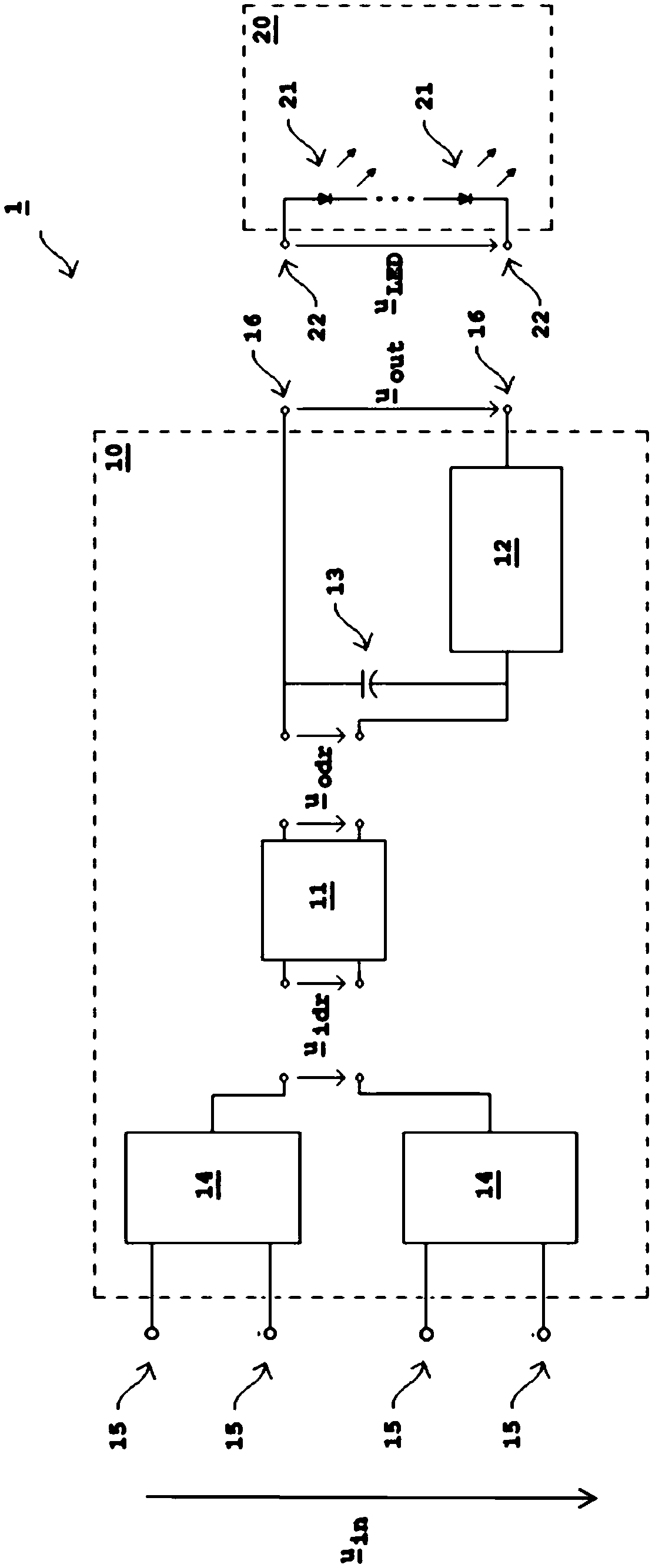
[0047] refer to figure 1 The schematic circuit diagram of the LED lamp 1 according to the present invention is described in detail.

[0048] The lamp driver 10 comprises an LED driver 11, a ripple current suppression circuit 12, an electrolytic capacitor 13, two filament circuits 14 each having two pins forming a voltage input 15, a voltage input 15 and a volta...


PUM


Abstract

The invention provides a lamp driver (10) for an LED lamp (1). The lamp driver comprises: an LED driver (11) for driving an LED (21); a voltage input terminal (15) adapted to connect the LED driver (11) to an electronic ballast of a fluorescent lamp as a power source; a voltage output terminal (16) adapted to connect the LED (21) to the LED driver (11); and a ripple current suppression circuit (12) connected in series between the LED driver (11) and the voltage output terminal (16) and used to suppress ripple current.

Description

technical field [0001] The invention relates to a lamp driver for an LED lamp and to an LED lamp for arrangement in a fluorescent lamp luminaire. Background technique [0002] Fluorescent lamps have become well known and widely used lighting devices as an effective replacement for incandescent light bulbs. However, with the advent of LED lamps (LED is short for Light Emitting Diode), more efficient and long-lasting lighting devices are available. Furthermore, compared to fluorescent lamps, the materials of LED lamps are safer since, for example, mercury is not required. Therefore, there is a need to replace existing fluorescent lamps with LED lamps, preferably without changing the entire luminaire or fixture. [0003] Currently available fluorescent lamp luminaires usually include a so-called electronic ballast (also called Electronic Control Gear, ECG) for regulating and limiting the current supplied to the fluorescent lamp. Electronic ballasts typically operate lamps at...

Claims


Application Information

Patent Timeline
IPC IPC(8): H05B33/08H05B37/00H05B44/00
CPCH05B45/3578H05B47/10
Inventor 范鑫李志峰
Owner LEDVANCE GMBH
Features
  • R&D
  • Intellectual Property
  • Life Sciences
  • Materials
  • Tech Scout
  • Unparalleled Data Quality
  • Higher Quality Content
  • 60% Fewer Hallucinations
Learn More