Double-shaft transmission high-efficiency quail egg shell removing machine

A biaxial transmission and quail egg technology, applied in the direction of food science, etc., can solve the problems of different degrees of pressure on quail eggs, difficult separation of egg white and eggshell, and incomplete shelling, so as to improve the efficiency of shelling and improve the peeling efficiency. Completeness of the shell and the effect of improving the integrity rate

Inactive Publication Date: 2018-11-16
宿州恒臣机械设备有限公司
View PDF4 Cites 4 Cited by
  • Summary
  • Abstract
  • Description
  • Claims
  • Application Information

AI Technical Summary

Problems solved by technology

[0004] The purpose of the present invention is to provide a high-efficiency quail egg shelling machine driven by two shafts. Through the action of the shell pressing device and the shelling device, it has the advantages of high integrity rate of the protein after shelling, improved shelling efficiency, and high shelling degree. It solves the problems of different degrees of pressure on existing quail eggs, difficult separation of egg whites and eggshells, low efficiency of shelling, and incomplete shelling.

Method used


Image

  • Double-shaft transmission high-efficiency quail egg shell removing machine
  • Double-shaft transmission high-efficiency quail egg shell removing machine
  • Double-shaft transmission high-efficiency quail egg shell removing machine

Examples


Embodiment Construction

[0035] The following will clearly and completely describe the technical solutions in the embodiments of the present invention with reference to the accompanying drawings in the embodiments of the present invention. Obviously, the described embodiments are only some, not all, embodiments of the present invention. Based on the embodiments of the present invention, all other embodiments obtained by persons of ordinary skill in the art without creative efforts fall within the protection scope of the present invention.

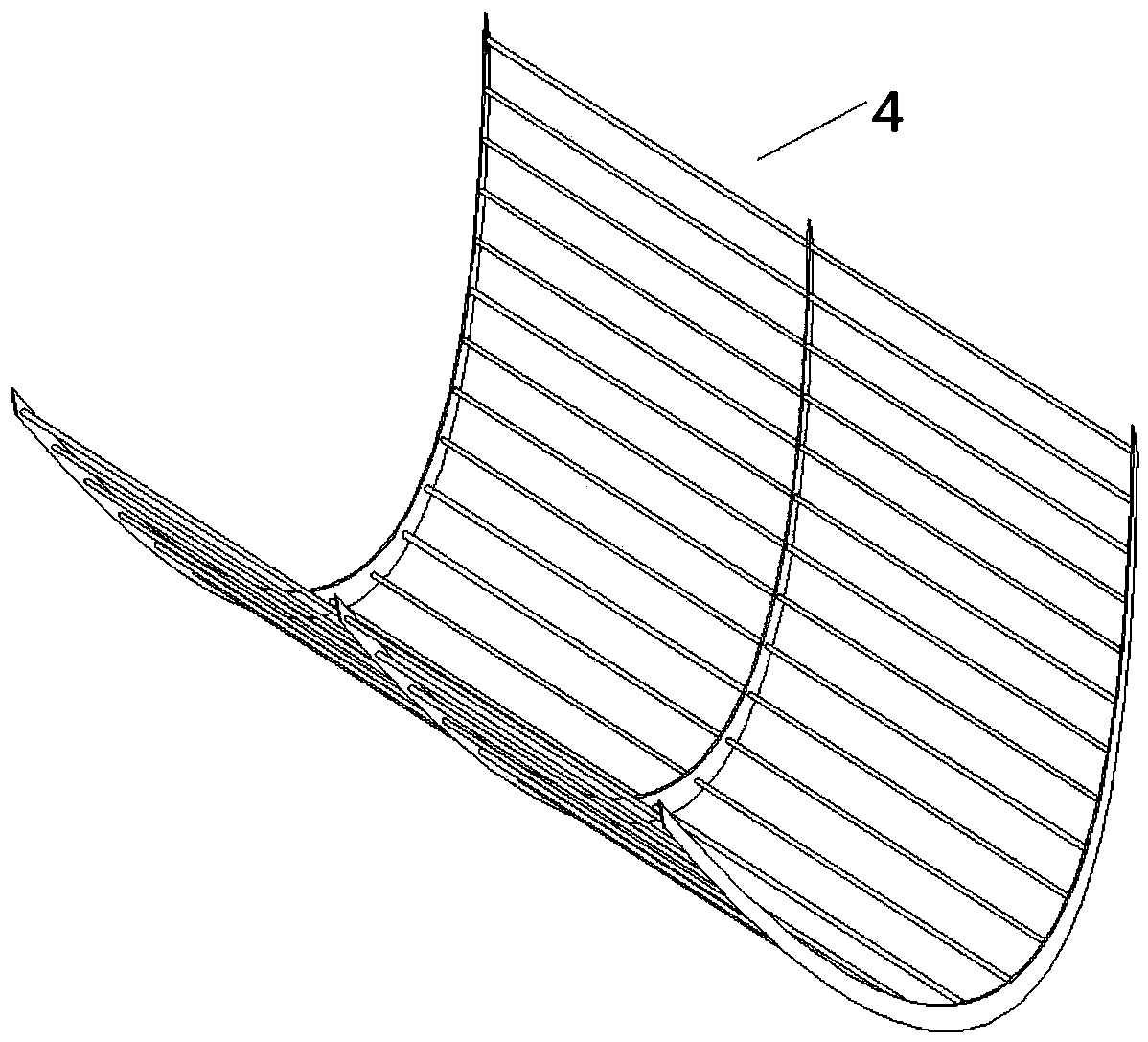
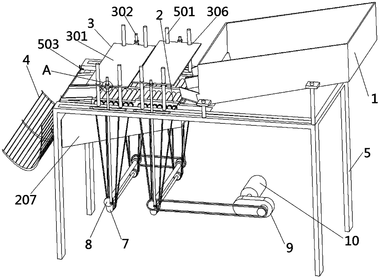
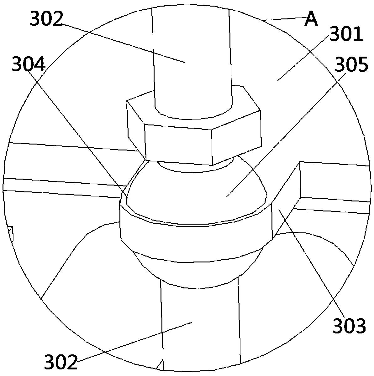
[0036] see Figure 1-9 Shown, the present invention is a kind of high-efficiency quail egg peeling machine of biaxial transmission, comprises feeding hopper 1, peeling device 2, pressing shell device 3, discharge fence 4 and frame 5, and feeding hopper 1, peeling The device 2, the shell pressing device 3 and the discharge fence 4 are fixedly installed on the frame 5 in sequence;

[0037] like figure 1 As shown, the shelling device 2 includes a first shelling plat...


PUM


Abstract

The invention discloses a double-shaft transmission high-efficiency quail egg shell removing machine, and relates to the technical field of automatic shell removing machines. The double-shaft transmission high-efficiency quail egg shell removing machine comprises a feeding hopper, a shell removing device, a shell pressing device, a discharge fence and a machine frame, wherein the feeding hopper, the shell removing device, the shell pressing device and the discharge fence are sequentially and fixedly mounted on the machine frame; the shell removing device comprises two shell removing platforms;shell removing rollers are rotatably connected to each shell removing platform; first gears are respectively arranged on the two end surfaces of each shell removing roller; the shell pressing devicecomprises pressing plates and pressing shafts; the pressing plates are in rotating cooperation via through holes; driven shafts are rotatably connected between the shell removing device and the machine frame; second gears and first sprockets are arranged on the driven shafts; the circumferential side surface of each second gear is in meshing transmission with two first gears; and the other ends ofthe pressing shafts are in rotatable cooperation with limiting columns of main rotating shafts. According to the double-shaft transmission high-efficiency quail egg shell removing machine disclosed by the invention, through the effects of the shell pressing device and the shell removing device, the reciprocating position for pressing quail egg shells is stationary, so that each quail egg is subjected to the same deformation, and the double-shaft transmission high-efficiency quail egg shell removing machine has the advantages of being high in the egg white integrity rate of quail eggs of whichthe shells are removed, high in shell removing efficiency and high in shell removing degree.

Description

technical field [0001] The invention belongs to the technical field of automatic shelling machines, in particular to a high-efficiency quail egg shelling machine driven by two shafts. Background technique [0002] The individual quail eggs are very small, and it is inconvenient to shell them. The traditional method is to use manual shelling, which is time-consuming and laborious, and the shelling efficiency is low, which cannot meet the shelling production requirements of modern quail egg industrialization. In the existing quail egg shelling machine, the up and down reciprocating force of the shell pressing device is within a range, which easily causes uneven stress on each quail egg, resulting in some quail eggs being crushed, and some quail eggs being crushed. The shell is not broken; there are also the problems that the egg white and the shell of the quail egg cannot be separated, and the shelling efficiency is low and the shelling degree is not complete. [0003] In vie...

Claims


Application Information

Patent Timeline
Patent Type & Authority Applications(China)
IPC IPC(8): A23L15/00
CPCA23L15/00
Inventor 毛臣臣
Owner 宿州恒臣机械设备有限公司
Why Eureka
Try Eureka