A high-efficiency shearing device for plate parts

A technology of shearing device and plate parts, which is applied in the direction of shearing device, attachment device of shearing machine, shearing machine equipment, etc., can solve problems such as inapplicability, and achieve the effects of avoiding secondary cutting, high safety, and avoiding collision

Active Publication Date: 2019-12-20
徐州欧美国林人造板有限公司
View PDF8 Cites 0 Cited by
  • Summary
  • Abstract
  • Description
  • Claims
  • Application Information

AI Technical Summary

Problems solved by technology

[0003] Most of the existing shearing machines adopt the desktop design. The plate is placed on the working surface for shearing. , resulting in inapplicability to longer plate shears

Method used


Image

  • A high-efficiency shearing device for plate parts
  • A high-efficiency shearing device for plate parts
  • A high-efficiency shearing device for plate parts

Examples


Embodiment 1

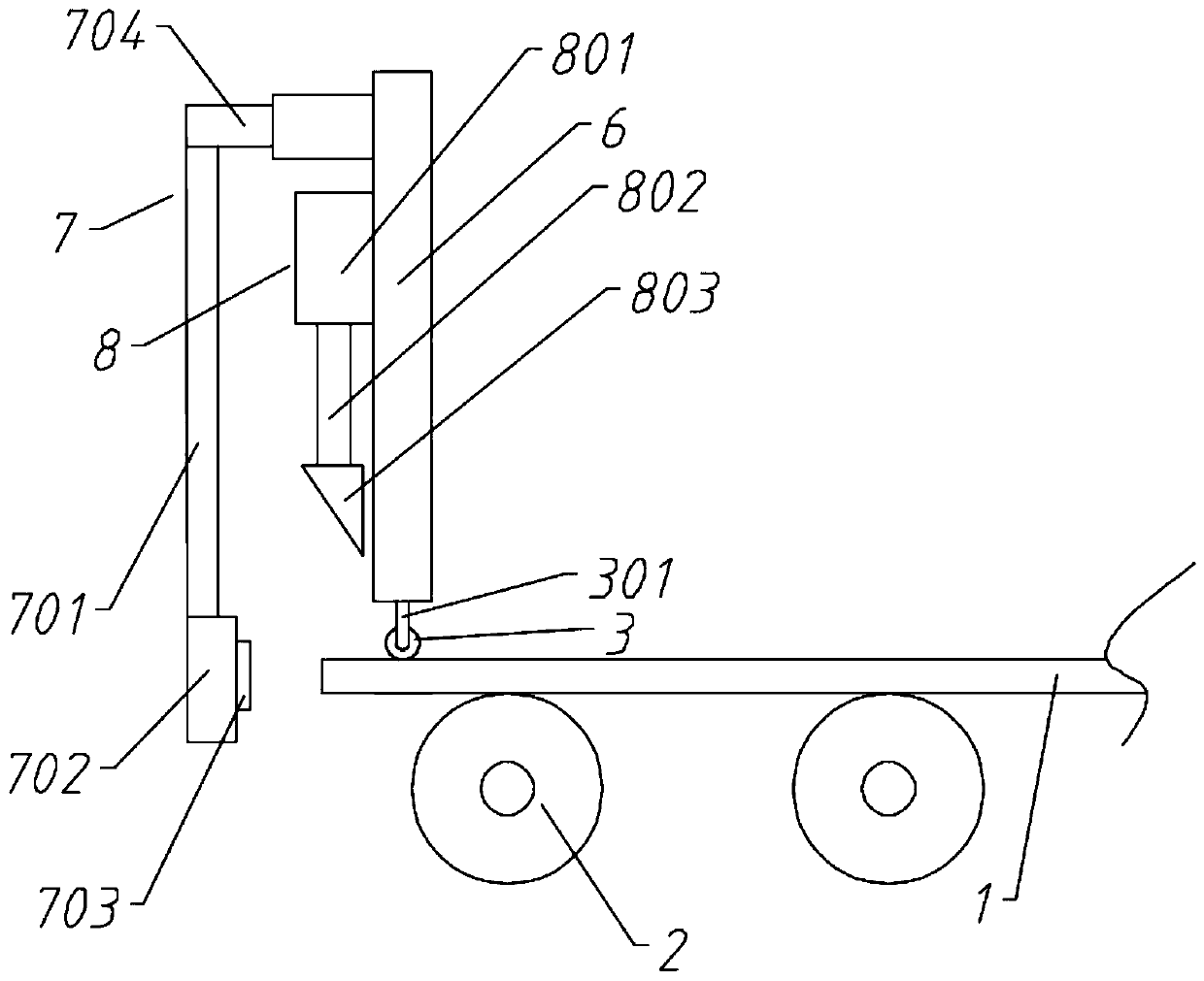
[0036] A high-efficiency shearing device for plates, including a driving roller shaft 2, a limit assembly 7 and a shear assembly 8;

[0037] The driving roller shaft 2 is evenly laid under the plate 1; the driving roller shaft 2 is externally connected with a motor, and the motor is provided with a power supply;

[0038] A support plate 6 is provided above the forward end of the plate 1, and a limit assembly 7 and a shear assembly 8 are provided on the front side of the support plate 6;

[0039] The limit assembly 7 includes an adjustment cylinder 704, a connecting rod 701 and a limit block 702. The adjustment cylinder is installed horizontally on the support plate 6. One end of the connection rod 701 is connected to the telescopic end of the adjustment cylinder 704, and the other end extends vertically downward and connects to the limit block. Block 702; the limit block 702 is provided with a contact switch corresponding to the plate 1;

[0040] The cutting assembly 8 includ...

Embodiment 2

[0042] A high-efficiency shearing device for plates, including a driving roller shaft 2, a limit assembly 7 and a shear assembly 8;

[0043] The driving roller shaft 2 is evenly laid under the plate; the driving roller shaft 2 is connected with a motor, and the motor is provided with a power supply;

[0044] A support plate 6 is provided above the forward end of the plate 1, and a limit assembly 7 and a shear assembly 8 are provided on the front side of the support plate 6;

[0045] The limiting assembly 7 includes an adjusting cylinder 704, a connecting rod 701 and a limiting block 702. The adjusting cylinder 704 is horizontally installed on the support plate 6. One end of the connecting rod 701 is connected to the end plate, and the other end extends vertically downward and connects to the limiting block 702. ; The limit block 702 is provided with a contact switch corresponding to the plate 1;

[0046] The shearing assembly 8 includes a hydraulic cylinder 801 and a cutter 8...

Embodiment 3

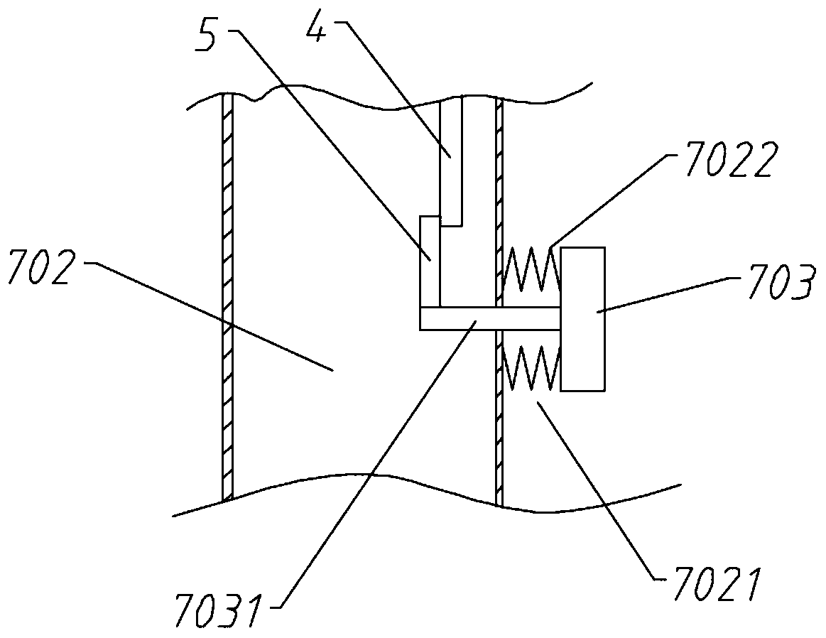
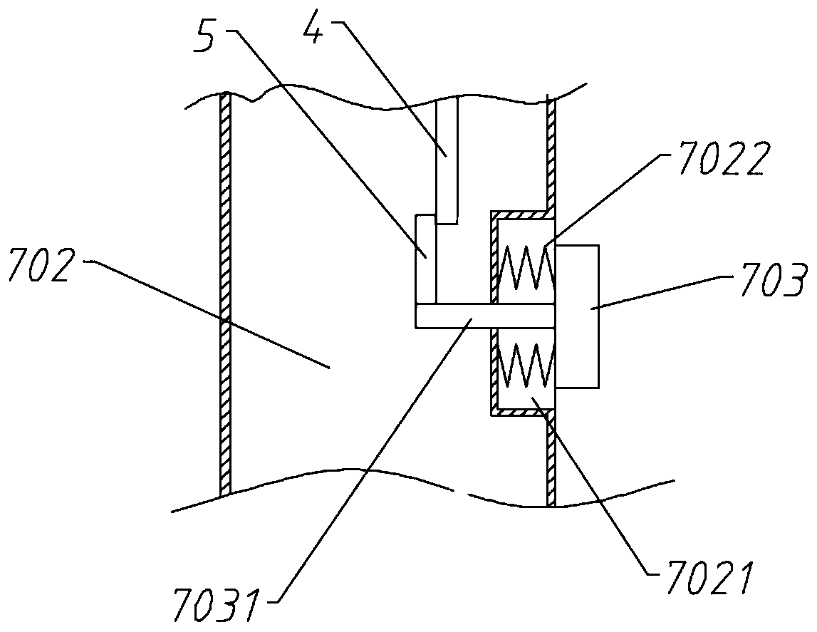
[0052] The limit block 702 is provided with a groove 7021 corresponding to the pressure block, and the spring 7022 is arranged between the groove 7021 and the pressure block to prevent overpressure. The limit block 702 plays a blocking role after the pressure block 703 enters the groove 7021 completely.


PUM


Abstract

The invention relates to the technical filed of plate machining, in particular to an efficient plate shearing device for plate pieces. Through a contact switch, shifting between driving and positioning can be achieved, and with cooperation with a limiting assembly, displacement of the plate pieces can be limited, and therefore displacement of the plate pieces are the same, and secondary cutting isavoided. The limiting assembly achieves position adjustment and positioning through an adjusting cylinder, and therefore shearing requirements of different spaces of the plate pieces can be met. An upper compression roller is arranged at the cutting end, and therefore the plate pieces can be effectively limited without influence on cutting, and the problems caused by plate body upwarp during cutting are avoided. A delayed communicating device is arranged, when the contact switch is connected with driving roll shaft power, delayed communication is carried out, enough recovery time is providedfor a cutting assembly, collision with the cutting assembly caused by plate piece forward movement is avoided, and security is high.

Description

technical field [0001] The invention relates to the technical field of plate shearing, in particular to a high-efficiency shearing device for plates. Background technique [0002] Shearing machine is a kind of forging machinery, the main function is the metal processing industry, the products are widely used in aviation, light industry, metallurgy, chemical industry, construction, shipbuilding, automobile, electric power, electrical appliances, decoration and other industries, providing the required special Machinery and complete equipment. [0003] Most of the existing shearing machines adopt the desktop design. The plate is placed on the working surface for shearing. , resulting in inapplicability to longer plate shears. Contents of the invention [0004] (1) Solved technical problems [0005] The purpose of the present invention is to overcome the deficiencies in the prior art, and provide a high-efficiency shearing device for plates. [0006] (2) Technical solution...

Claims


Application Information

Patent Timeline
Patent Type & Authority Patents(China)
IPC IPC(8): B23D15/06B23D15/14B23D33/02
CPCB23D15/06B23D15/14B23D33/02
Inventor 戎耀
Owner 徐州欧美国林人造板有限公司
Why Eureka
Try Eureka