Glue feeding device and method for injection molding water tank

A glue feeding and water tank technology, which is applied in the field of glue feeding devices for injection molding water tanks, can solve problems such as flow lines and shrinkage of water tanks, and achieve the effects of solving shrinkage, reducing injection molding pressure, and improving pressure holding

Active Publication Date: 2018-11-16
ZHUHAI GREE PRECISION MOLD CO LTD +2
View PDF3 Cites 2 Cited by
  • Summary
  • Abstract
  • Description
  • Claims
  • Application Information

AI Technical Summary

Problems solved by technology

[0005] Therefore, the technical problem to be solved by the present invention is to overcome the defect that the glue feeding method of the injection-molded water tank in the prior art is easy to produce flow marks and shrinkage problems on the appearance surface of the water tank, thereby providing a water tank that can eliminate the flow marks on the appearance surface of the water tank. Glue feeding device and glue feeding method for injection molding water tank and shrinkage problem

Method used


Image

  • Glue feeding device and method for injection molding water tank
  • Glue feeding device and method for injection molding water tank
  • Glue feeding device and method for injection molding water tank

Examples


Embodiment 1

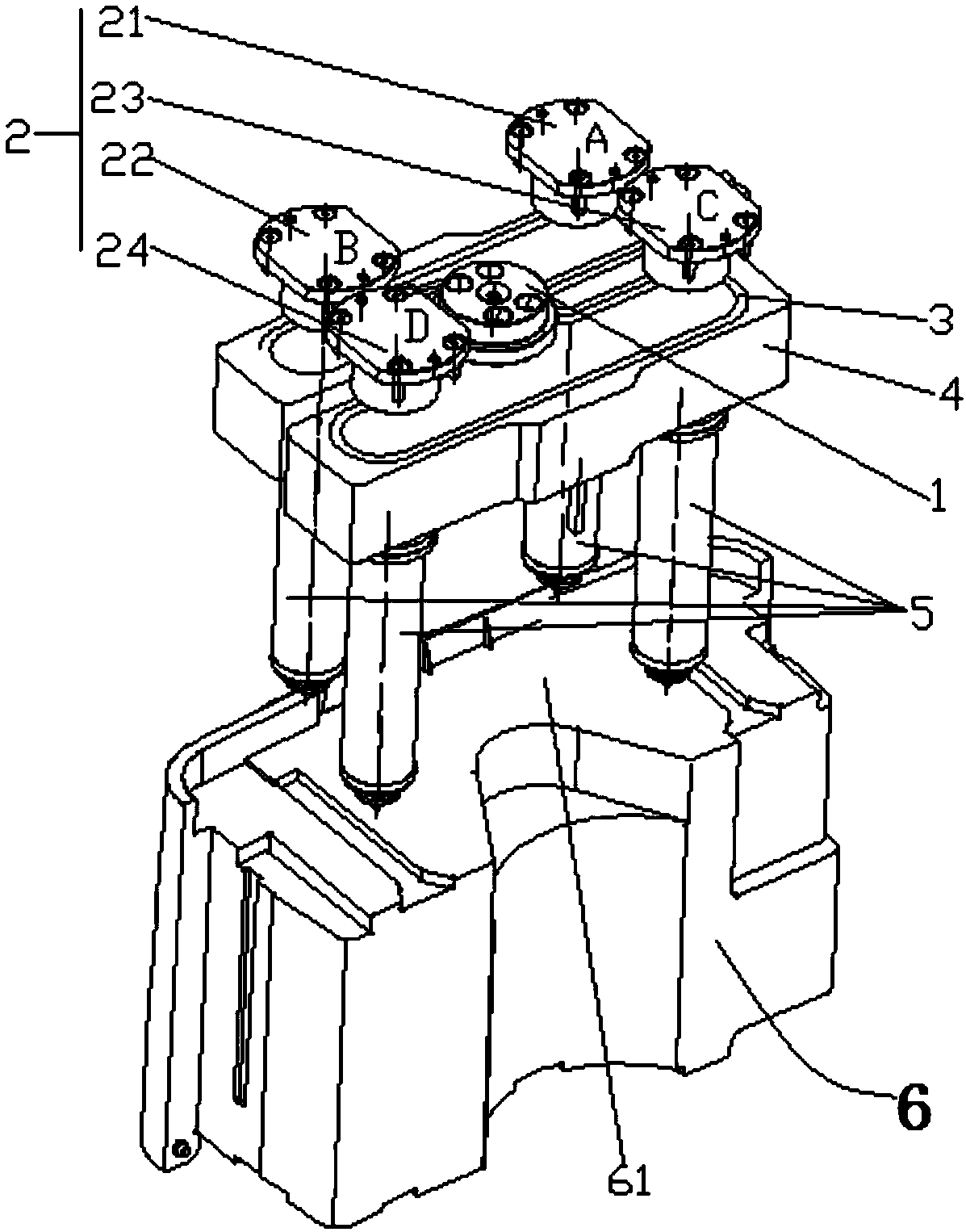
[0038] Such as Figure 2-3 Shown, a kind of glue feeding device for injection molding water tank 6 of the present invention comprises

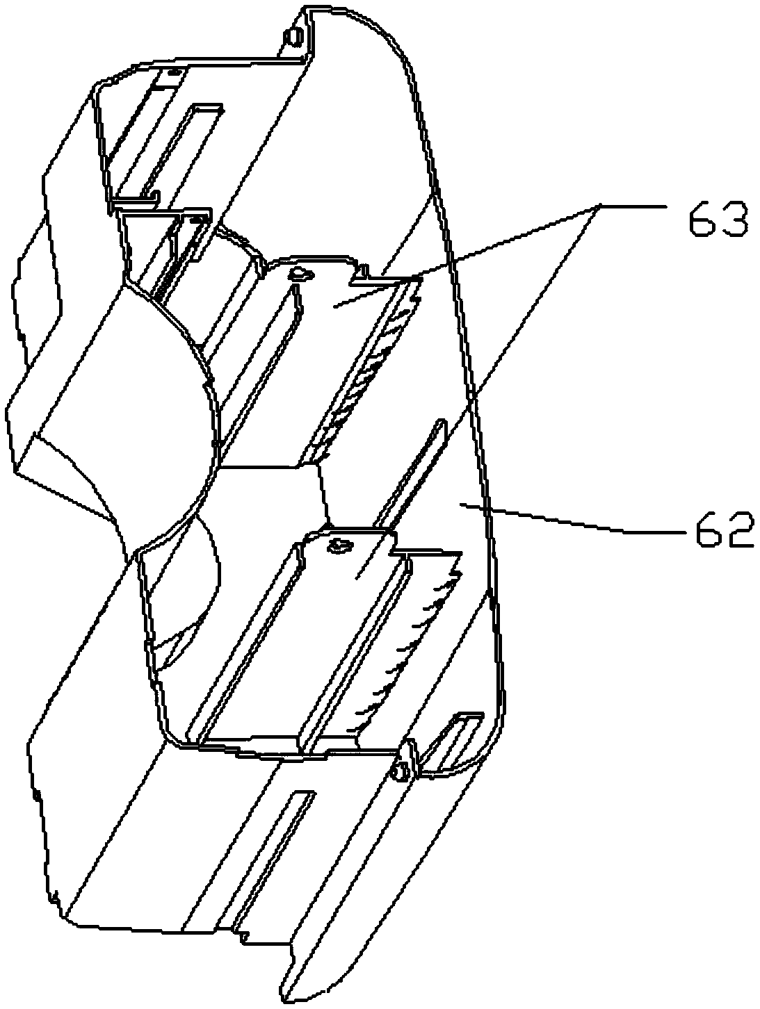
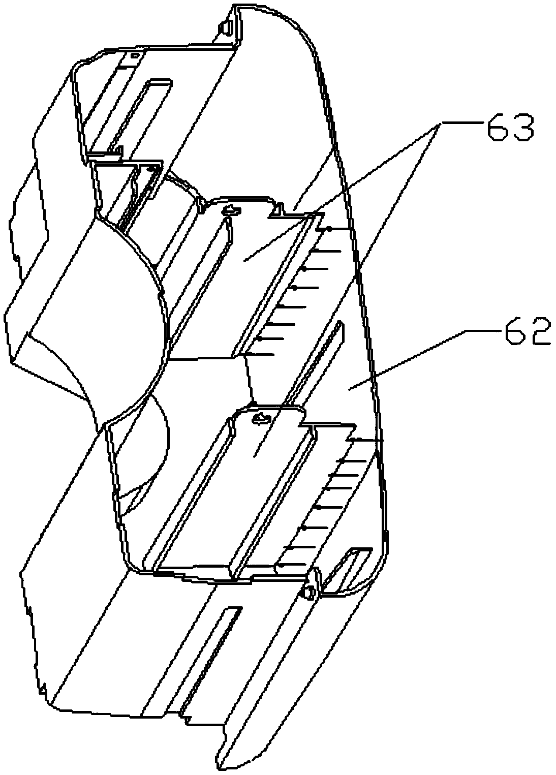
[0039] There are at least four needle valve nozzles arranged in two rows, including the first row of needle valve nozzles arranged close to the appearance surface 62 of the water tank 6, and the second row of needle valve nozzles arranged far away from the appearance surface 62 of the water tank 6, The needle valve nozzle is evenly placed on the bottom 61 of the water tank 6 to feed glue;

[0040] The glue injection structure injects glue into each of the needle valve nozzles.

[0041] Since the first row of needles and valves are set close to the appearance surface 62 of the water tank 6, the rubber material first fills the cavity where the appearance surface 62 of the water tank 6 is located, and then fills the cavity where the rib 63 is located, thereby effectively avoiding the appearance of the product. Flow lines are produced on the sur...


PUM


Abstract

The invention provides a glue feeding device for an injection molding water tank. The glue feeding device comprises at least four needle valve nozzles and a glue injection structure, wherein the at least four needle valve nozzles are arranged and are arranged in two rows; the needle valve nozzles comprise a first row of needle valve nozzles which are arranged at a part close to an appearance surface of the water tank and a second row of needle valve nozzles which are arranged at a part far away the appearance surface of the water tank; the needle valve nozzles are arranged at the bottom of thewater tank and are used for feeding glue; the glue injection structure is used for injecting the glue into each needle valve nozzle. A glue feeding method for the injection molding water tank, provided by the invention, comprises the following steps: a flow channel setting step: arranging four points or more than four points of flow channels at the bottom of the water tank, and arranging the flowchannels in two rows; arranging the first row at the part close to the appearance surface of the water tank and arranging the second row at the part far away the appearance surface of the water tank;a glue feeding control step: controlling the first row of flow channels and the second row of flow channels to feed the glue. By adopting the glue feeding device and method for the injection moldingwater tank, provided by the invention, the defects of flow lines, shrinkage, welding lines, mold burrs and the like on the appearance surface of the water tank can be effectively eliminated.

Description

technical field [0001] The invention relates to the field of injection molding, in particular to a glue feeding device and a glue feeding method for injection molding water tanks. Background technique [0002] The water tank includes a bottom, an appearance surface arranged on the bottom, and a reinforcing rib with one end connected to the inner side of the appearance surface. In the prior art, when injecting water tanks, there are usually two ways to feed the glue: [0003] The first is to use a cold runner at the bottom of the water tank to feed the glue. This method of glue feeding requires manual cutting of the nozzle material during production, resulting in nozzle waste, which is not conducive to automatic production, and will lead to water tank failure due to improper operation of the nozzle. There is a risk of water leakage. [0004] The second is to use a needle-point hot runner at the bottom of the water tank to inject glue at a single point. When using this singl...

Claims


Application Information

Patent Timeline
Patent Type & Authority Applications(China)
IPC IPC(8): B29C45/27B29C45/28B29C45/76
CPCB29C45/27B29C45/28B29C45/281B29C45/76B29L2031/712
Inventor 陈土辉夏庆雷徐少华翁卫军王云飞郭峰林强黄国军蔡国旗
Owner ZHUHAI GREE PRECISION MOLD CO LTD
Why Eureka
Try Eureka