
Oil heater cooling fin positioning buffer device and conveying system with same

A technology of cooling fins and oil fins, which is applied to conveyor objects, transportation and packaging, etc., can solve problems such as affecting the conveying speed of oil fins, and achieve the effect of ensuring normal conveying speed.

Pending Publication Date: 2018-11-16
ZHUHAI GREE INTELLIGENT EQUIP CO LTD +1
View PDF0 Cites 1 Cited by
  • Summary
  • Abstract
  • Description
  • Claims
  • Application Information

AI Technical Summary

Problems solved by technology

[0004] The main purpose of the present invention is to provide a positioning and buffering device for oil heat sinks and a conveying system with the same, to at least solve the problem in the prior art that the normal conveying speed of oil heat sinks is affected due to oil heat sinks waiting to be grasped on the conveying line question

Method used


Image

  • Oil heater cooling fin positioning buffer device and conveying system with same
  • Oil heater cooling fin positioning buffer device and conveying system with same
  • Oil heater cooling fin positioning buffer device and conveying system with same

Examples


Embodiment Construction

[0038] It should be noted that, in the case of no conflict, the embodiments of the present invention and the features in the embodiments can be combined with each other. The present invention will be described in detail below with reference to the accompanying drawings and examples.

[0039]In order to enable those skilled in the art to better understand the solutions of the present invention, the following will clearly and completely describe the technical solutions in the embodiments of the present invention in conjunction with the drawings in the embodiments of the present invention. Obviously, the described embodiments are only It is an embodiment of a part of the present invention, but not all embodiments. Based on the embodiments of the present invention, all other embodiments obtained by persons of ordinary skill in the art without making creative efforts shall fall within the protection scope of the present invention.

[0040] According to the embodiment of the presen...


PUM


Abstract

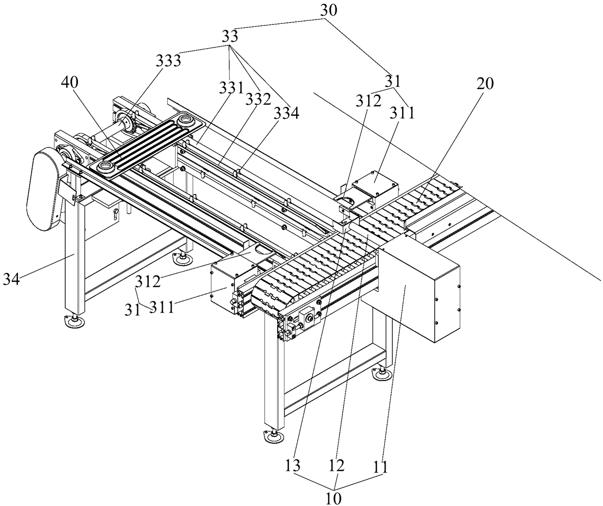
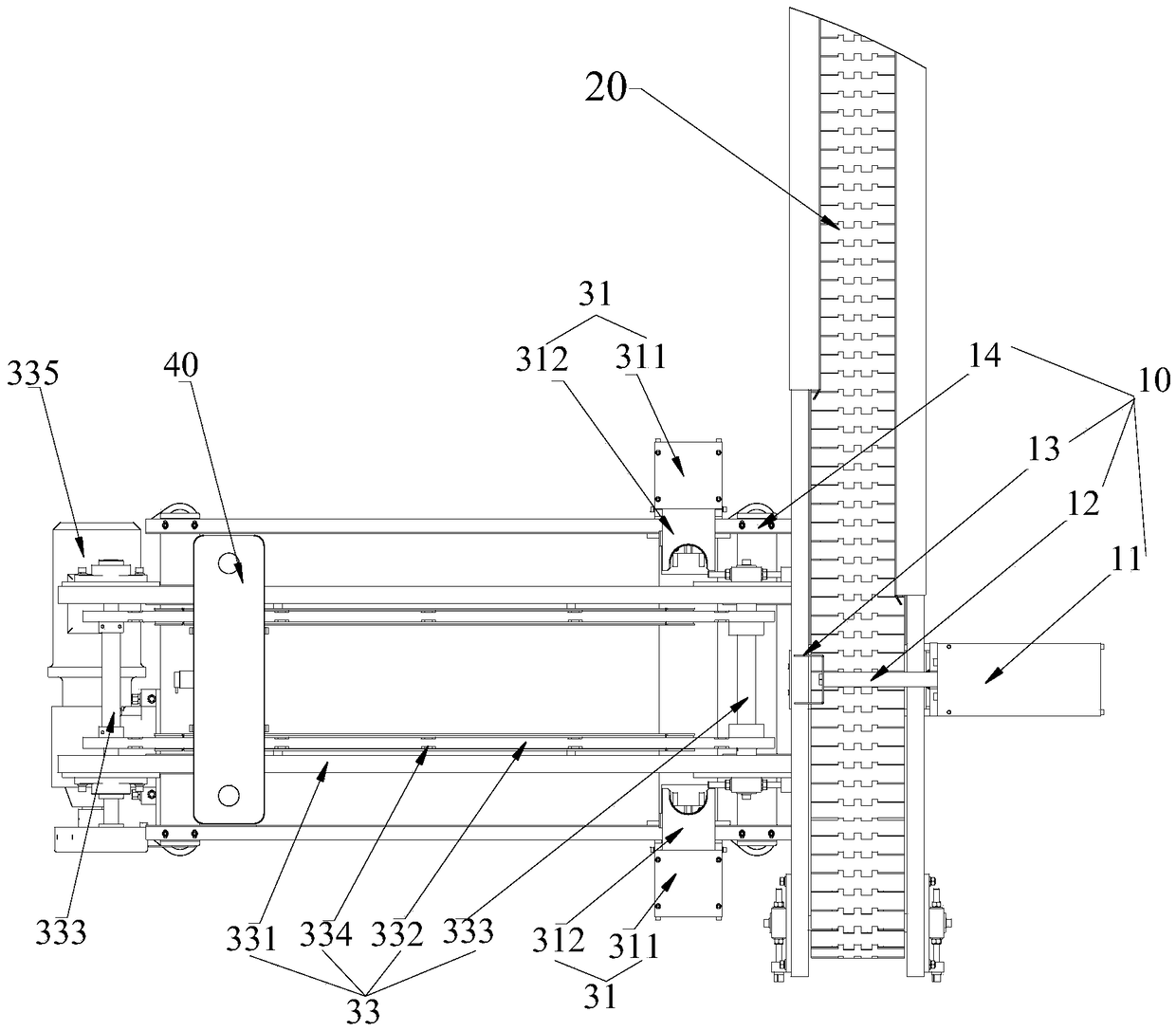
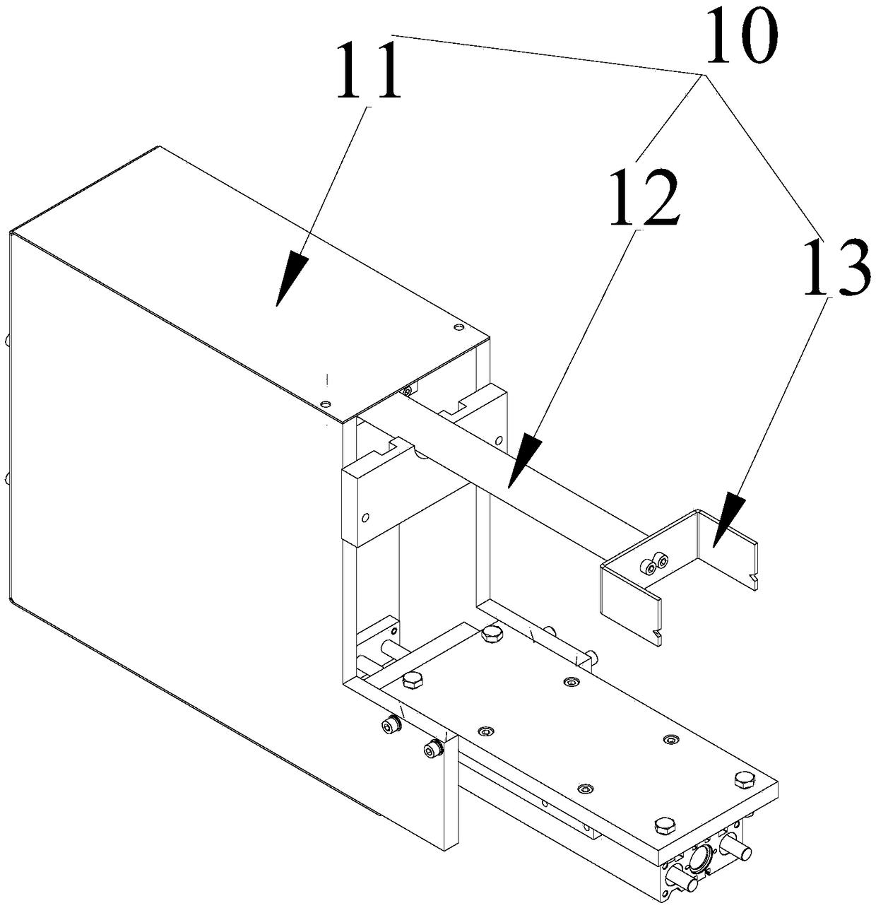
The invention provides an oil heater cooling fin positioning buffer device and a conveying system with the same. The oil heater cooling fin positioning buffer device comprises a pushing mechanism anda buffer mechanism; the pushing mechanism is arranged on an oil heater cooling fin conveying line; the buffer mechanism and the pushing mechanism are oppositely arranged; the oil heater cooling fin conveying line is used for conveying oil heater cooling fins to move along a preset trajectory; and the pushing mechanism is used for pushing the oil heater cooling fins onto the buffer mechanism for buffer and grabbing by a robot when the oil heater cooling fins move to a first preset position opposite to the pushing mechanism. The oil heater cooling fins have no need to stop on the conveying linefor grabbing, so that the normal conveying speed of the oil heater cooling fin conveying line is guaranteed. The problem of influence on normal conveying speed of the oil heater cooling fins by grabbing waiting of the oil heater cooling fins on the conveying line in the prior art is solved.

Description

technical field [0001] The invention relates to the field of grease production equipment, in particular to a grease radiator positioning and buffering device and a conveying system having the same. Background technique [0002] At present, in the production of oily sheets, after the seam welding process is completed, the oily sheets are grabbed by robots and enter the next process. When the robot grabs the oil film, it needs to position the oil film. In the prior art, cylinders are used for jacking up and cylinders on both sides are used for clamping and positioning to wait for the robot to grab. One station can only cache one oil heat sink. [0003] However, during the conveying process of the oil film, due to the non-stop transportation of the seam welding finished product line, there are too many oil film backflows. When one oil film is grabbed, the subsequent oil film can only wait on the conveying line, which affects the transportation. The normal conveying speed of t...

Claims


Application Information

Patent Timeline
IPC IPC(8): B65G47/82B65G47/90
CPCB65G47/82B65G47/90Y02D10/00
Inventor 欧积晋尹勋举彭永红孙涛
Owner ZHUHAI GREE INTELLIGENT EQUIP CO LTD
Learn More