Compound berth-alongside device for elevated trestle

An elevated trestle and berthing technology, which is applied in the field of ships, can solve problems such as limited buffering efficiency, damage to the trestle box structure, and inability to berth ships, so as to improve safety and reliability, expand berthing space, and increase anti-collision effects Effect

Inactive Publication Date: 2018-11-16
CHINA SHIP SCIENTIFIC RESEARCH CENTER (THE 702 INSTITUTE OF CHINA SHIPBUILDING INDUSTRY CORPORATION)
View PDF4 Cites 0 Cited by
  • Summary
  • Abstract
  • Description
  • Claims
  • Application Information

AI Technical Summary

Problems solved by technology

However, there are the following outstanding defects when the current dock berthing device is directly applied to the elevated trestle: (1), it is difficult to provide sufficient buffer performance in the limited space on the side of the elevated trestle, because the height of the elevated trestle box is very small, If the wharf berthing device is directly used, the rubber ball cannot be used due to its large scale, and the cushioning effect provided by the rubber tire or rubber fender is very limited due to the limited scale, that is, a single rubber material is used for berthing in a limited space It is difficult for the device to guarantee the safety of berthing ships; (2), point contact and concentrated force are likely to cause damage to the trestle bridge, because when various types of boats berth, usually a certain local area collides with the trestle box first, and the local rubber material itself Due to the limitation of scale, it is impossible to disperse the concentrated contact force at this point to a wider range, so it is easy to cause damage to the structure of the trestle box; (3), the type of berthing boats is greatly restricted, due to the small height of the trestle box, A single conventional rubber material is only limited to this height, which makes it impossible for boats with a small freeboard to berth. When a boat with a large freeboard is berthed, it will affect the safety of berthing because it goes too deep into the trestle deck area.

Method used


Image

  • Compound berth-alongside device for elevated trestle
  • Compound berth-alongside device for elevated trestle
  • Compound berth-alongside device for elevated trestle

Examples


Embodiment Construction

[0018] The specific embodiments of the present invention will be further described below in conjunction with the accompanying drawings.

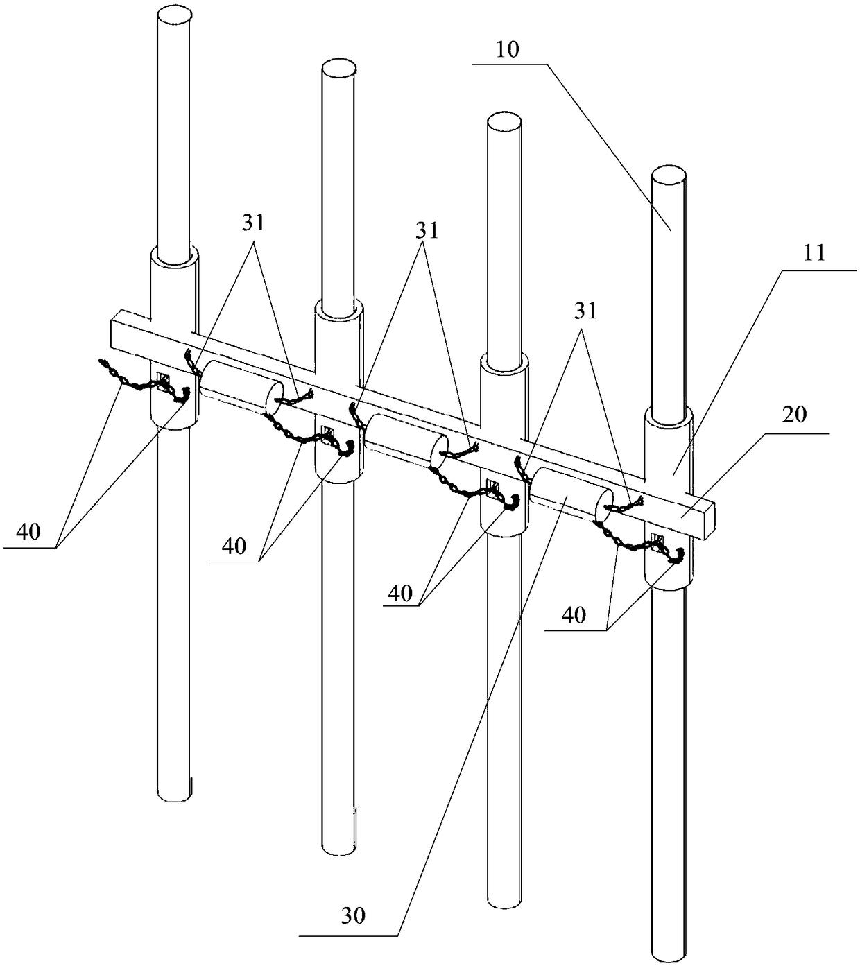
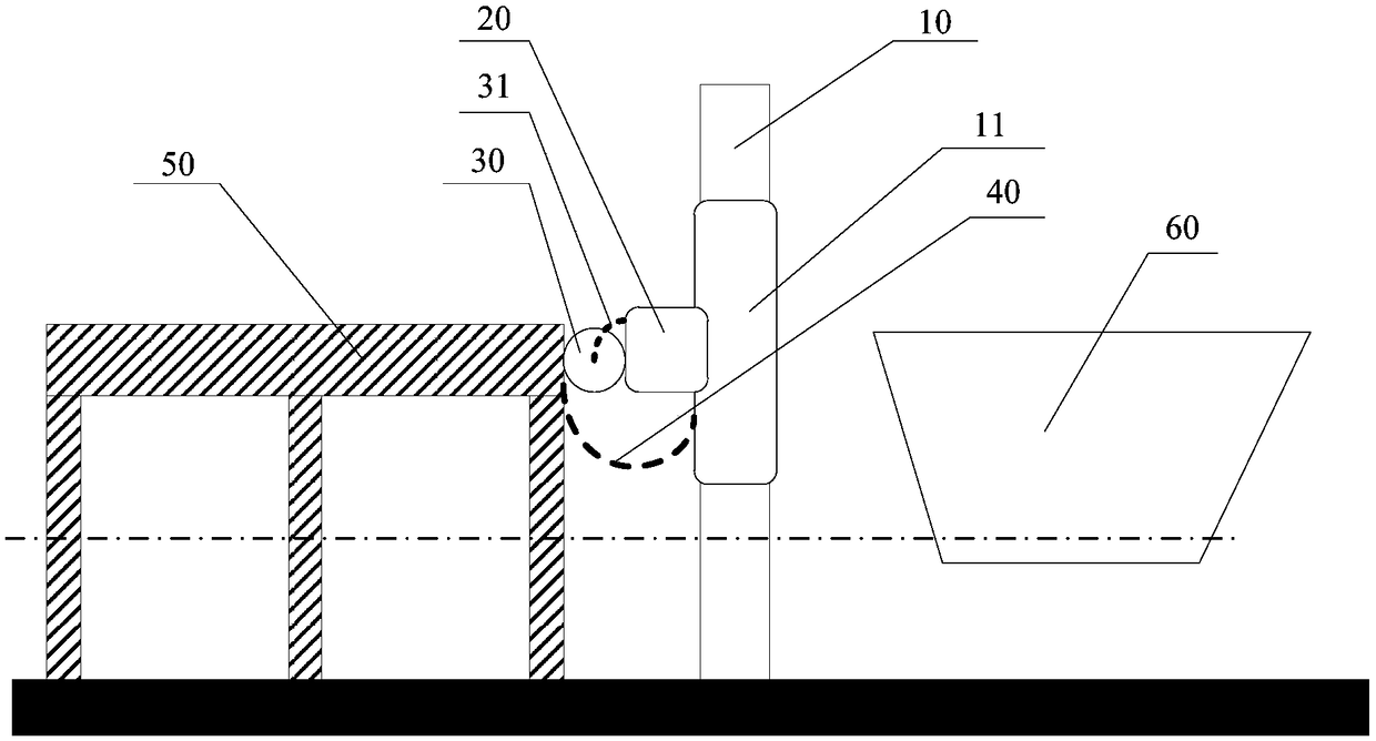
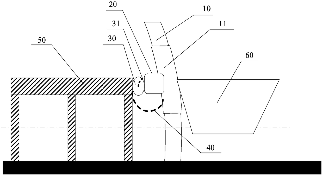
[0019] This application discloses a compound berthing device suitable for elevated trestles, please refer to figure 1 , the composite berthing device includes: N columns 10, beams 20 and several buffer pads 30, N≥2 and N is a positive integer, this application takes N=4 as an example, the specifications of N columns 10 are the same, N The uprights 10 are arranged in parallel. Normally, the distance between every two uprights 10 is equal. The distance between the uprights 10 is generally an empirical value, which is not limited in this application. The beam 20 vertically spans one side of the N columns 10 and is respectively connected with the N columns 10 to form a bent structure. The height of the entire bent structure is the height of each column, and the width of the entire bent structure is N The width formed by the uniform distribution...


PUM


Abstract

The invention discloses a compound berth-alongside device for an elevated trestle and relates to the technical field of ships. The compound berth-alongside device comprises N columns, a cross beam andbuffer mats, a buffer layer is wrapped on the outer side of each column, the columns are arranged in parallel, the cross beam perpendicularly stretches across one sides of the columns and forms bentstructures with the columns respectively, the buffer mats are arranged between every two columns and connected with the cross beam, and the buffer mats are in contact with the cross beam and a trestlebox body respectively. According to the compound berth-alongside device for the elevated trestle, a single cross beam is adopted to connect a single row of columns into an entirety, small distributedbuffer mats are arranged between the cross beam and the trestle box body so that a tertiary compound berth-alongside energy absorption structure can be formed, the collision force during ship berthing is effectively dispersed, and the requirement of safety berthing alongside in limited berthing space for the elevated trestle is sufficiently met.

Description

technical field [0001] The invention relates to the technical field of ships, in particular to a compound berthing device suitable for elevated trestles. Background technique [0002] With the continuous development and construction of marine islands and reefs in my country, it is necessary to build a certain length of elevated trestles around the islands and reefs for the transportation of personnel and goods from barges to islands and reefs. The bridge section box of the elevated trestle is supported above the water surface by pile legs, one end is connected to the shore through a springboard, and the other end of the trestle box side needs to be equipped with suitable berthing devices for safe berthing and docking of various types of ships. transport. In order to ensure that the boat can safely berth on the trestle bridge, its berthing device should be able to provide appropriate elastic stiffness so as to effectively absorb the collision energy. [0003] At present, th...

Claims


Application Information

Patent Timeline
Patent Type & Authority Applications(China)
IPC IPC(8): E02B3/26E02B3/00
CPCE02B3/00E02B3/26Y02A30/30
Inventor 汤明刚郑文慧叶永林吴小峰顾学康程小明
Owner CHINA SHIP SCIENTIFIC RESEARCH CENTER (THE 702 INSTITUTE OF CHINA SHIPBUILDING INDUSTRY CORPORATION)
Why Eureka
Try Eureka