Button panel

A button and panel technology, applied in the field of kitchen and bathroom products, to achieve the effect of reducing collision deformation, reducing collision, and convenient installation

Pending Publication Date: 2018-11-16
TAIZHOU FENGHWA COPPER IND
View PDF1 Cites 1 Cited by
  • Summary
  • Abstract
  • Description
  • Claims
  • Application Information

AI Technical Summary

Problems solved by technology

[0005] The purpose of the present invention is to solve the above-mentioned problems in the prior art, and propos

Method used


Image

  • Button panel
  • Button panel
  • Button panel

Examples


Embodiment 1

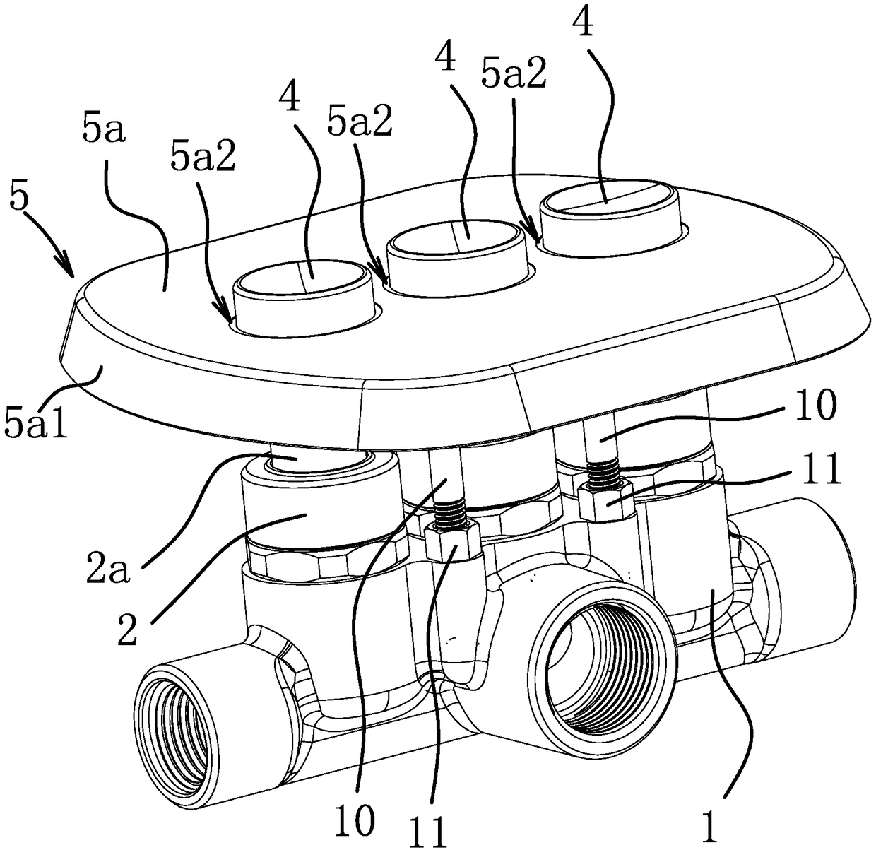
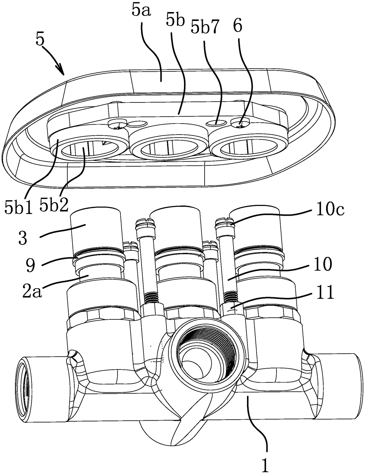
[0053] Such as Figure 1-Figure 10 As shown, a button panel is installed outside the control valve. The control valve includes a valve body 1. The valve body 1 is provided with a button valve core 2. The button valve core 2 includes an inner core and a valve stem 2a. Press the valve stem 2a to make the button Spool 2 moves. For the sake of clarity, this embodiment takes the valve body 1 as a reference, the end close to the valve body 1 is the inner end, and the end far away from the valve body 1 is the outer end. A connecting rod 9 is fixed on the outer end of the valve rod 2a, and the connecting rod 9 is used to lengthen the length of the valve rod 2a, and the connecting rod 9 is connected with a sealing cap 3. The lower end of the connecting rod 9 is sheathed and fixed on the valve rod 2a, the connecting rod 9 is provided with a threaded section 9a, and the sealing cap 3 is provided with a threaded part 3a corresponding to the threaded section 9a. The sealing cap 3 is slee...

Embodiment 2

[0063] The structure of the button part 4 is different from that of Embodiment 1. The button part 4 includes a cylindrical button body, the button body ends protrude from the button hole 5a2, and the inner end of the button body 4 is provided with a shallow groove, and the bottom surface of the shallow groove is against the sealing surface. On the sealing plate 3b of the cap 3. A retaining ring 4a3 is arranged on the outer surface of the inner end of the button, and the spring 8 abuts against the retaining ring 4a3 so that the button body is pressed against the sealing cap 3 . Other structures are the same as in Embodiment 1.

Embodiment 3

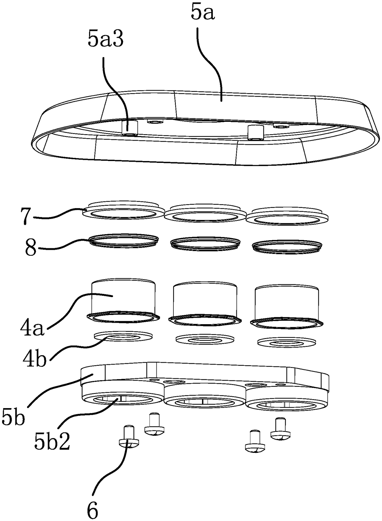
[0065] The panel part 5 includes a cover plate 5a, the cover plate 5a is provided with a button hole 5a2, the outer end of the button part 4 protrudes from the button hole 5a2, and the inner end surface of the cover plate 5a is provided with a connecting post 5a3, and the connecting post 5a3 is provided with a clamping post. hole 5b7, the connecting end 10b of the fixing rod 10 is inserted into the fastening hole 5b7 and fixed. The spacer ring 7 is fixed on the cover plate 5a, and the guide ring 7a is inserted into the button hole 5a2. That is, the button seat 5b is omitted in the structure of the first embodiment, and the other structures are the same as those of the first embodiment. When assembling on-site, screw the cap 3 onto the connecting rod 9, put the spring 8 outside the button cover 4a, then put the button cover 4a on the cap 3, and then fix the cover plate with the spacer 7 5a is installed on the fixing rod 10. During the fixing process, the button cover 4a protru...


PUM


Abstract

The invention provides a button panel and belongs to the technical field of kitchen and bath supplies. Through the button panel, the problem that noise is generated easily in the using process of button parts of an existing button panel is solved. The button panel is mounted on a control valve. The control valve comprises button valve elements. The button panel comprises a panel part. The panel part is provided with button holes. The button parts are slidably mounted in the button holes. The button panel furnace comprises springs. The two ends of each spring act on the panel part and the corresponding button part. Each button part is buckled to the corresponding button valve element. Through the button panel, the noise generated by the button parts in the using process can be reduced. Moreover, the button panel is convenient to install.

Description

technical field [0001] The invention belongs to the technical field of kitchen and sanitary products, and relates to a button panel. Background technique [0002] The faucet is an indispensable water supply terminal in daily life. For the beauty of home decoration, the pipeline of the faucet is often installed inside the wall, under the ground and under the washing table. In addition, the valve body and valve core of the faucet are also hidden inside the wall, under the ground and under the cleaning table, and only the spout and control button or control handle are set outside. This kind of faucet is called a hidden valve faucet. . The concealed valve faucet is generally fixed in the pre-buried hole. Taking the concealed valve faucet installed in the wall as an example, the water inlet pipe and the water outlet pipe are fixed in the wall, and the pre-buried hole is set on the wall, and the control valve of the faucet is placed in the pre-buried hole. The inside is connect...

Claims


Application Information

Patent Timeline
IPC IPC(8): F16K31/60
CPCF16K31/60
Inventor 李法余
Owner TAIZHOU FENGHWA COPPER IND
Why Eureka
Try Eureka