Metal part drying machine

A technology for metal parts and dryers, applied in dryers, drying, non-progressive dryers, etc., can solve the problems of uneven heating of metal parts, affecting the drying of metal parts, inconsistent drying degree, etc., and achieve cooling Fast, easy to maintain, easy to collect and save the effect

Active Publication Date: 2018-11-16
福州云睿自动化设备有限公司
View PDF9 Cites 2 Cited by
  • Summary
  • Abstract
  • Description
  • Claims
  • Application Information

AI Technical Summary

Problems solved by technology

In the current metal parts drying device, the metal parts are heated unevenly during the drying process, and the drying degree is inconsistent, and the stirring shaft is often used to stir and dry the metal parts. The metal parts are easy to stick to the stirring shaft, which affects the drying of the metal parts. Dry
[0003] The utility model patent with the application number 201721271376.1 discloses a drying device for metal parts, including a drying box and a cooling cylinder. There are 3-6 drying plates in the drying box from top to bottom. An electric heating wire is buried inside the drying plate. One end of the drying plate is connected to the inner wall of the drying box through a spring, and the other end is connected to the eccentric wheel outside the drying box through a connecting rod. There is no need for a stirring shaft in the machine, and it does not affect the advantages of drying metal parts. However, this kind of device is directly heated by the electric heating wire inside the drying plate, and the thermal power consumption is high. If the metal parts have water, it will affect the drying effect, and It has many moving parts and is prone to failure

Method used


Image

  • Metal part drying machine
  • Metal part drying machine
  • Metal part drying machine

Examples


Embodiment Construction

[0033] In the description of the present invention, positional relationships such as "upper" and "lower" are based on the accompanying drawings figure 1 In terms of. The terms "first" and "second" are used for descriptive purposes only, and cannot be understood as indicating or implying relative importance or implicitly specifying the quantity of indicated technical features.

[0034] The technical solution of the present invention will be described in detail below in conjunction with the embodiments and the accompanying drawings.

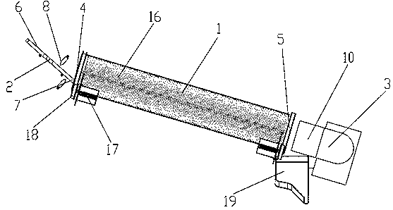
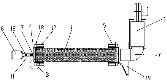
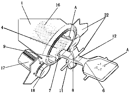
[0035] like Figure 1~3 As shown, a metal parts dryer includes a drum 1, a conveying mechanism 2 arranged above the drum 1, and a drying mechanism 3 arranged below the drum 1. The drum 1 is arranged obliquely, and There is a first inlet 4, a first outlet 5 is provided below, and the conveying mechanism 2 is arranged obliquely, a second inlet 6 is provided above, and a second outlet 7 is provided below, and the second outlet 7 is located at the fi...


PUM


Abstract

The invention discloses a metal part drying machine. The metal part drying machine comprises a roller, a conveying mechanism arranged on the upper side of the roller and a drying mechanism arranged onthe lower side of the roller. The roller is inclined. A first inlet is arranged on the upper side of the roller, and a first outlet is arranged on the lower side of the roller. The conveying mechanism is inclined. The upper side of the conveying mechanism is provided with a second inlet, and the lower side of the conveying mechanism is provided with a second outlet. The second outlet is located in the first inlet. The conveying mechanism is provided with a high-pressure air spray gun used for conducting pre-blow-drying on cleaned parts. Multiple groups of blocking pieces are arranged in the roller. The drying mechanism is located on the lower side of the roller and arranged at the position of the first outlet. The drying mechanism is a hot air blowing device capable of blowing out high-speed hot air. According to the metal part drying machine, a high-pressure air spray gun is adopted to conduct pre-blow-drying, so that the drying efficiency is improved; a motor directly drives the roller to rotate, the structure is simple, the fault rate is low, and maintenance is convenient; hot air blowing is adopted to dry the surfaces of the metal parts, after drying is completed, cooling is rapid, and collection and storage are facilitated.

Description

technical field [0001] The invention relates to the technical field of metal part processing equipment, in particular to a metal part dryer. Background technique [0002] In the production process of metal parts, it is generally necessary to dry the metal parts. The drying of metal parts is one of the important steps that affect the quality of metal parts. The degree of drying of metal parts directly reflects its shelf life. In the current metal parts drying device, the metal parts are heated unevenly during the drying process, and the drying degree is inconsistent, and the stirring shaft is often used to stir and dry the metal parts. The metal parts are easy to stick to the stirring shaft, which affects the drying of the metal parts. Dry. [0003] The utility model patent with the application number 201721271376.1 discloses a drying device for metal parts, including a drying box and a cooling cylinder. There are 3-6 drying plates in the drying box from top to bottom. An e...

Claims


Application Information

Patent Timeline
Patent Type & Authority Applications(China)
IPC IPC(8): F26B11/04F26B21/00F26B25/00
CPCF26B11/04F26B21/004F26B25/00
Inventor 陈智
Owner 福州云睿自动化设备有限公司
Why Eureka
Try Eureka