New energy vehicle

A new energy vehicle, cavity technology, applied to electric vehicles, vehicle components, vehicle connectors, etc., can solve problems such as electric shock and loose plugs

Inactive Publication Date: 2018-11-16
福州和信城电子科技有限公司
View PDF0 Cites 6 Cited by
  • Summary
  • Abstract
  • Description
  • Claims
  • Application Information

AI Technical Summary

Problems solved by technology

[0002] With the development of science and technology and the progress of society, the country has been promoting the development of high technology. In the field of new energy, there has always been a relatively difficult technical problem, that is, there is a risk of electric shock when ordinary new energy vehicle charging piles are charged at high voltage. At the same time Ordinary charging equipment adopts a simple plug-in method, which causes the plug to loosen during the charging process. This device effectively solves this problem

Method used


Image

  • New energy vehicle
  • New energy vehicle
  • New energy vehicle

Examples


Embodiment Construction

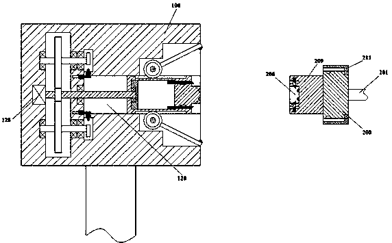
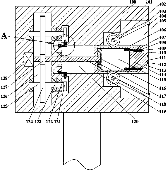
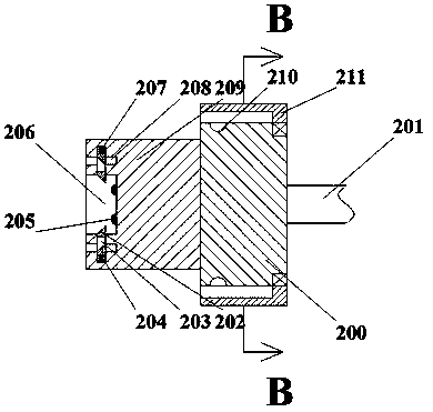
[0018] like Figure 1-Figure 5 As shown, a new energy vehicle of the present invention includes a charging pile 100 and a plug joint 200. The charging pile 100 is provided with a first sliding chamber 120 with an opening to the right, and the left end wall of the first sliding chamber 120 is There is a first cavity 126 inside, and a second cavity 105 communicating with the first sliding cavity 120 is arranged symmetrically to the right in the opening of the left end wall of the charging pile 100, and the first sliding cavity 120 can be Sliding left and right is provided with a sliding frame 114, the upper and lower end walls of the sliding frame 114 are symmetrically provided with racks 106, and the right side end wall of the sliding frame 114 is fixedly equipped with a bump 111, and the upper and lower end walls of the bump 111 A chute 113 is symmetrically arranged inside, and a second sliding chamber 115 is arranged in the sliding frame 114, and a sliding block 116 is provid...


PUM


Abstract

The invention discloses a new energy vehicle comprising a charging pile and a plug joint. The charging pile is provided with a first sliding cavity with an opening facing the right; and a first cavityis arranged in the left end wall of the first sliding cavity. Second cavities that are communicated with the first sliding cavity and have openings facing the right are arranged in the left end wallsof the charging pile symmetrically. A sliding rack sliding left and right is arranged in the first sliding cavity; tooth bars are arranged in the upper end wall and the lower end wall of the slidingrack symmetrically. A lug is fixedly installed on the right end wall of the sliding rack; skewed slots are formed in the upper end wall and the lower end wall of the lug symmetrically; and a second sliding cavity is arranged in the sliding rack. The new energy vehicle having a simple structure is operated conveniently. Delayed electrification is realized by using a mechanical structure during theplugging process; an oscillating rod is driven by one same power source to lock a plug, so that the equipment practicability is enhanced; and time sequence cooperation among all procedures is utilizedingeniously during the application process, so that the equipment reliability is improved.

Description

technical field [0001] The invention relates to the field of new energy, in particular to a new energy vehicle. Background technique [0002] With the development of science and technology and the progress of society, the country has been promoting the development of high technology. In the field of new energy, there has always been a relatively difficult technical problem, that is, there is a risk of electric shock when ordinary new energy vehicle charging piles are charged at high voltage. At the same time Ordinary charging equipment adopts a simple plug-in method, which causes the plug to loosen during the charging process. This device effectively solves this problem. Contents of the invention [0003] The technical problem to be solved by the present invention is to provide a new energy vehicle, which can solve the above-mentioned problems in the prior art. [0004] The present invention is achieved through the following technical solutions: A new energy vehicle of th...

Claims


Application Information

Patent Timeline
IPC IPC(8): H01R13/627H01R13/633H01R13/639H01R13/70B60L11/18
CPCH01R13/639H01R13/6278H01R13/633H01R13/701H01R2201/26
Inventor 俞一文
Owner 福州和信城电子科技有限公司
Why Eureka
Try Eureka