[0013] The technical solutions in the embodiments of the present invention will be clearly and completely described below in conjunction with the accompanying drawings in the embodiments of the present invention. Obviously, the described embodiments are only a part of the embodiments of the present invention, rather than all the embodiments. Based on the embodiments of the present invention, all other embodiments obtained by those of ordinary skill in the art without creative work shall fall within the protection scope of the present invention.
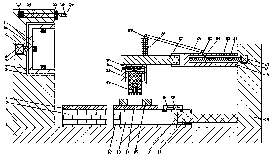
[0014] See Figure 1-3 , An embodiment provided by the present invention: an integrated automated ultrasonic device, comprising a worktable 1, the upper end of the worktable 1 is fixedly connected with a first support 12, the upper end of the first support 12 is provided with a A conveyor belt 14, the left side of the first support platform 12 is provided with a second support platform 3 fixedly connected to the upper end surface of the workbench 1, and the upper end surface of the second support platform 3 is provided with a second conveyor belt 4, the The upper end surface of the first conveyor belt 14 is provided with a gear 15 to be tested. The left side of the second support platform 3 is provided with a first support column 2 fixedly connected to the upper end surface of the work platform 1, and the first support column 2 is provided with a Drive space 7, the left end wall of the drive space 7 is fixedly connected with a drive motor 8, the right end wall of the drive space 7 is provided with a rotating space 5 communicating with the outside space, the right end of the drive motor 8 is dynamically connected with a drive shaft 9 The right end of the drive shaft 9 passes through the right end wall of the drive space 7 and is located in the rotation space 5. The right end of the drive shaft 9 is fixedly connected to a detection block 6, and the right end of the detection block 6 is provided with a detection slot 11. An ultrasonic detection device 10 is fixedly connected to the upper, lower and left sides of the groove 11, a hydraulic space 13 is provided in the first support table 12, and a pushing plate 16 is slidably connected to the hydraulic space 13, and the right end of the pushing plate 16 is fixedly connected There is a push rod 17, the right end of the push rod 17 passes through the right end wall of the hydraulic space 13 and is located in the external space, the right end of the push rod 17 is fixedly connected to a second support column 18, the lower end of the second support column 18 and the workbench 1 The upper end surface is slidingly connected, the second support column 18 is provided with a transmission space 20, the right end wall of the transmission space 20 is fixedly connected with a transmission motor 21, and the left end surface of the second support column 18 is fixedly connected with a fixed rod 19, The upper end of the fixed rod 19 is provided with an inverted T-shaped groove 23, the inverted T-shaped groove 23 is connected to the external space, the left end of the transmission motor 21 is dynamically connected to a transmission shaft 22, and the left end of the transmission shaft 22 passes through the transmission space The left end wall of 20 is located in the inverted T-shaped groove 23. The left end of the transmission shaft 22 is rotatably connected with the left end wall of the inverted T-shaped groove 23. The upper end of the transmission block 23 is fixedly connected with a first connecting block 25. The upper end of the first connecting block 25 passes through the upper end of the inverted T-shaped groove 23 and is located in the external space. The upper end of the first connecting block 25 A connecting rod 26 is rotatably connected, and the left end of the fixed rod 19 is rotatably connected with a transmission rod 27, the upper end of the transmission rod 27 is fixedly connected with a connecting post 28, and the upper end of the connecting post 28 is fixedly connected with a second connecting block 29, The left end of the connecting rod 26 is rotatably connected with the second connecting block 29, the lower end of the transmission rod 27 is fixedly connected to a fixed block 30, the fixed block 30 is provided with a lifting mechanism 50, and the lifting mechanism 50 is provided with a lock The tightening mechanism 49, the upper end surface of the first support platform 12 is fixedly connected with a hydraulic pump 52, and the upper end surface of the first support platform 12 A hydraulic pipe 51 connecting the hydraulic spaces 13 at the left and right ends of the pushing plate 16 is provided, and a lighting device 56 is fixedly connected to the right end of the first support column 2.
[0015] Advantageously, the lifting mechanism 50 includes a lifting space 32, a spiral space 33 is provided in the left end wall of the lifting space 32, and a screw motor 31 is fixedly connected to the left end wall of the spiral space 33, and the right end of the screw motor 31 is dynamically connected There is a sliding screw 34. The right end of the sliding screw 34 passes through the right end wall of the spiral space 33 and is located in the lifting space 32. The right end of the sliding screw 34 is rotatably connected with the right end wall of the lifting space 32. The sliding screw 34 is A part of the lifting space 32 is symmetrically screwed and connected to a translation block 35. The lower end of the translation block 35 is rotatably connected with a translation rod 36. The lifting space 32 is slidably connected with a partition 38, and the upper end of the partition 38 A rotating block 37 is fixedly connected, the lower end of the translation rod 36 is rotatably connected with the rotating block 37, and a lifting column 39 is fixedly connected to the lower end surface of the partition 38, whose function is to control and adjust the vertical movement of the lifting column 39 in a controllable manner.
[0016] Advantageously, the locking mechanism 49 includes a locking space 45, a lifting space 41 is provided in the upper end wall of the locking space 45, and a lifting motor 40 is fixedly connected to the upper end wall of the lifting space 41. The end face is power-connected with a lifting shaft 42. The lower end of the lifting shaft 42 passes through the lower end wall of the lifting space and is rotatably connected with the lower end wall of the locking space 45. The lower end of the lifting shaft 42 is fixedly connected with a cam 43, the left and right ends of the cam 43 The contact transmission is connected to a locking block 44 which is slidably connected to the upper and lower end walls of the locking space 45. The front and rear walls of the locking space 45 are symmetrically connected to a limiting plate 47. The locking block 44. The front and rear faces of 44 are symmetrically connected with a limit block 46. The end of the limit block 46 away from the lifting shaft 42 is slidably connected to the locking space 45. The limit block 46 is fixedly connected to the end surface of the lifting shaft 42 with a spring 48. The end of the spring 48 close to the lifting shaft 42 is fixedly connected to the limiting plate 47, and its function is to connect the gear and the lifting column 39 together by the locking mechanism 49 when the lifting column 39 is lowered to the center of the gear.
[0017] Advantageously, the sliding screw 34 is provided with threads with opposite spiral directions at both ends, which function to enable the two translation blocks 35 to move relative to each other during the rotation of the sliding screw 34.
[0018] Advantageously, the lighting device 56 includes a base 55, the right end of the base 55 is fixedly connected with a lighting lamp 55, an energy block 53 is arranged in the upper end of the first support column 2, and the right end of the energy block 53 is connected to the The left end surface of the base station 55 is connected by a cable 54, and its function is to provide illumination for each operating mechanism on the worktable 1 to facilitate inspection.
[0019] Specific usage: In the work of the present invention, the first conveyor belt 14 causes the gear conveyor belt lifting column 39 to be directly underneath, the lifting mechanism 50 works, and the screw motor 31 works to drive the sliding screw 34 to rotate, thereby causing the translation block 35 to move relatively. The connection of the translation rod 36 pushes the rotating block 37 downward, the partition 38 moves downward, and the lifting column 39 enters the center of the gear. At this time, the motor 40 on the stage drives the cam 43 to rotate, and the locking block 44 is moved to both sides. The gear is pushed out to tension the gear, the lifting mechanism 50 works to drive the gear upwards, the transmission motor 21 works, drives the transmission shaft 22 to rotate, and the transmission block 24 moves to the right through the connecting rod 26 until the transmission rod 27 is pulled and fixed. The rod 19 is in a right-angle position. At this time, the hydraulic pump 52 works and moves the pushing plate 16 toward the left, thereby driving the second support column 18 to move to the left until the gear enters the detection slot 11, and the driving motor 8 works to drive the detection block 6 to rotate. When the ultrasonic testing device 10 works, the gear is tested in all directions. If it is qualified, the locking mechanism 49 puts the gear into the second conveyor belt 4. If it fails, the locking mechanism 49 returns the gear to the first conveyor belt 14, and then proceed. Next check.
[0020] For those skilled in the art, it is obvious that the present invention is not limited to the details of the foregoing exemplary embodiments, and the present invention can be implemented in other specific forms without departing from the spirit or basic characteristics of the present invention. Therefore, from any point of view, the embodiments should be regarded as exemplary and non-limiting. The scope of the present invention is defined by the appended claims rather than the above description, and therefore it is intended to fall within the claims. All changes within the meaning and scope of equivalent elements of are included in the present invention. Any reference signs in the claims should not be regarded as limiting the claims involved.