A Welding Device and Method for Improving Hook Defects in Friction Stir Welded Lap Joints

A technology for lap joints and hook defects, applied in the field of welding devices for improving friction stir welding lap joints, to achieve the effects of increasing effective load-bearing thickness, simple operation, and easy realization

Active Publication Date: 2020-09-01
SHENYANG AEROSPACE UNIVERSITY
View PDF6 Cites 0 Cited by
  • Summary
  • Abstract
  • Description
  • Claims
  • Application Information

AI Technical Summary

Problems solved by technology

[0005] In order to solve the problem of the upwardly bent "HOOK" existing in the friction stir lap welding in the prior art, which seriously affects the performance and quality of the joint, the present invention provides a welding device and method for improving the hook defect of the friction stir welding lap joint

Method used


Image

  • A Welding Device and Method for Improving Hook Defects in Friction Stir Welded Lap Joints
  • A Welding Device and Method for Improving Hook Defects in Friction Stir Welded Lap Joints
  • A Welding Device and Method for Improving Hook Defects in Friction Stir Welded Lap Joints

Examples


Embodiment 1

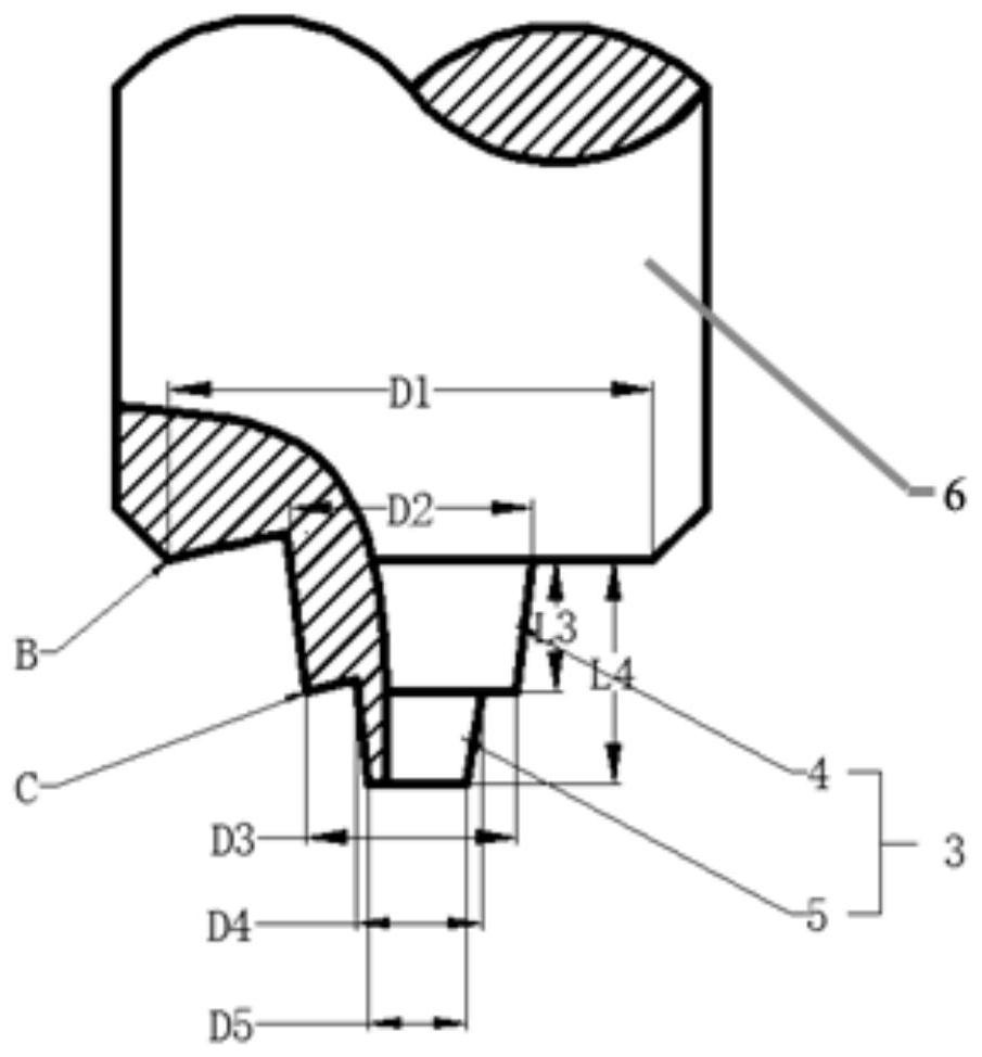
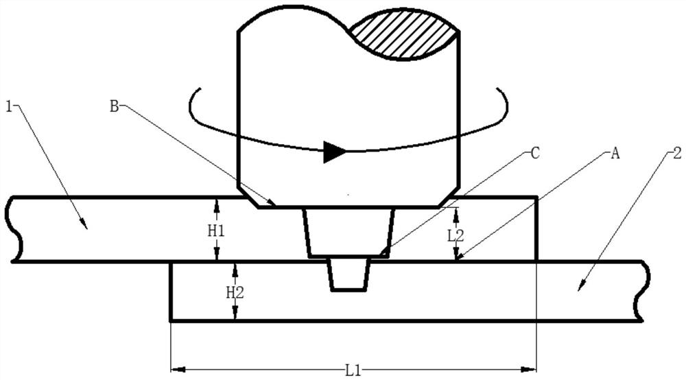
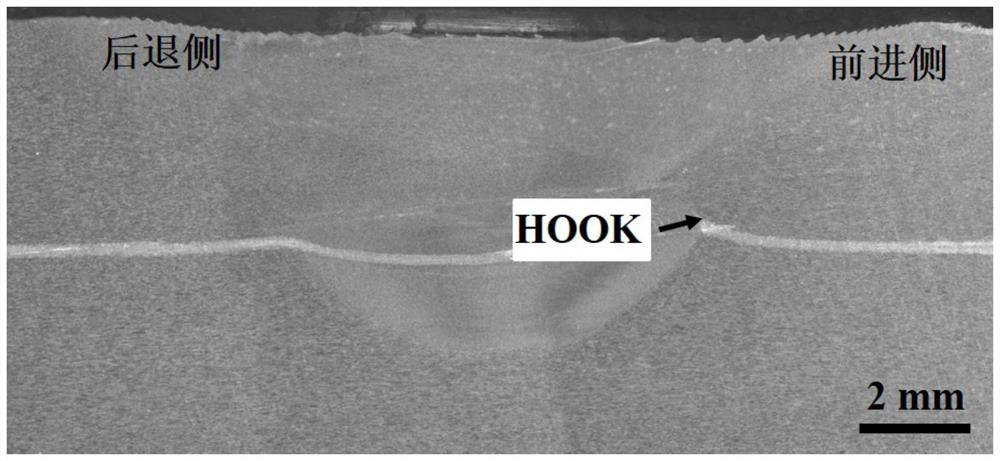
[0032] The first aluminum alloy plate to be welded with H1 = 4mm and the second aluminum alloy plate to be welded with H2 = 4mm are assembled with a lap joint structure to form the lap joint surface A, and the length L1 of the lap joint surface is selected as 15mm. Then use the above-mentioned welding device and welding method to carry out friction stir welding: the total length of the stirring needle L4=5.4mm, the length of the first-stage stirring needle L3=3.65mm, the downward pressure=0.2mm, the diameter of the upper and bottom surface of the first-stage stirring needle D2=8mm, Bottom diameter D3=8mm, upper bottom diameter D4=4mm of secondary stirring needle, lower bottom diameter D5=4mm, end surface of primary stirring needle is convex, shaft shoulder diameter D1=18mm, stirring head speed 1400r / min, welding The speed is 600mm / min. The microstructure analysis of the welded aluminum alloy sheet is as follows: image 3As shown, the results show that the "HOOK" in the joint ...

Embodiment 2

[0034] The first aluminum alloy plate to be welded with H1 = 4mm and the second aluminum alloy plate to be welded with H2 = 4mm are assembled with a lap joint structure to form the lap joint surface A, and the length L1 of the lap joint surface is selected as 15mm. Then use the above-mentioned welding device and welding method to carry out friction stir welding: the total length of the stirring needle L4=5.4mm, the length of the first-stage stirring needle L3=3.65mm, the downward pressure=0.2mm, the diameter of the upper and bottom surface of the first-stage stirring needle D2=6mm, Bottom surface diameter D3=6mm, upper bottom surface diameter D4=4mm of secondary stirring needle, lower bottom surface diameter D5=4mm, end surface shape of primary stirring needle is concave surface, shaft shoulder diameter D1=18mm, stirring head rotating speed is 2000r / min, welding speed It is 200mm / min. The microstructure analysis of the welded aluminum alloy sheet is as follows: Figure 4 As s...


PUM

PropertyMeasurementUnit
diameteraaaaaaaaaa
diameteraaaaaaaaaa

Abstract

The invention provides a welding device and method for improving hook-shaped defects of a friction stir welding overlap joint. The device comprises a stirring head and a motor connected with the stirring head. The stirring head is composed of a shaft shoulder and bottom two-stage stirring needles coaxially and integrally arranged with the shaft shoulder. The first-stage stirring needle and the second-stage stirring needle of the two-stage stirring needles are of a conical or cylindrical structure, the first-stage stirring needle is located above the second-stage stirring needle, and the diameter of the lower bottom surface of the first-stage stirring needle is larger than the diameter of the upper bottom surface of the second-stage stirring needle. The method comprises the steps of measuring geometric parameters of workpieces to be welded and the stirring head, fixing the workpieces to be welded, determining the position of welding, determining the depth of pressing and friction stir welding. By adopting the welding device and method for improving the hook-shaped defects of the friction stir welding overlap joint, an overlap joint with a "HOOK" shape and a horizontal or even slightly downward bending feature can be obtained, and the effective load bearing thickness of the joint can be significantly increased. In addition, the welding device and method for improving the hook-shaped defects of the friction stir welding overlap joint are simple in operation, easy to implement, and suitable for friction stir welding of overlap joint structures of various thicknesses.

Description

technical field [0001] The invention relates to the field of friction stir welding, in particular to a welding device and method for improving the hook defect of friction stir welding lap joints. Background technique [0002] Friction Stir Welding (FSW) technology, as a solid-phase joining technology, can avoid metallurgical defects such as pores and slag inclusions in fusion welding. However, when the friction stir welding technology is applied to the welding of lap joint structures, the original interface of the upper and lower plates will migrate under the action of the stirring head, and the original interface within the scope of the stirring needle will be destroyed, while the edge of the stirring needle will be destroyed. Part of the interface will bend in the vertical direction, forming the unique upward-bending hook defect in the friction stir welding lap joint, also known as the "HOOK" defect, which will cause the "effective thickness" of the plate to decrease, resu...

Claims


Application Information

Patent Timeline
Patent Type & Authority Patents(China)
IPC IPC(8): B23K20/12
CPCB23K20/1225B23K20/1255
Inventor 徐荣正崔盛林侯艳喜李慧
Owner SHENYANG AEROSPACE UNIVERSITY
Why Eureka
Try Eureka