
Banding strap automatic cutting machine

A cutting machine and automatic technology, which is applied to the parts and packaging of strapping machinery, so as to achieve the effect of high degree of automation and improvement of work efficiency

Pending Publication Date: 2018-11-20
KATOLEC AUTOMOTIVE SYST GUANGZHOU CO LTD
View PDF0 Cites 0 Cited by
  • Summary
  • Abstract
  • Description
  • Claims
  • Application Information

AI Technical Summary

Problems solved by technology

[0004] In view of the above situation, the present invention provides an automatic cable tie cutting machine, which can adjust the binding force, automatically cut off the excess part of the binding tie, solve the defects of manual binding, and improve production efficiency

Method used


Image

  • Banding strap automatic cutting machine
  • Banding strap automatic cutting machine
  • Banding strap automatic cutting machine

Examples


Embodiment Construction

[0022] The technical solutions of the present invention will be further described below with reference to the accompanying drawings and embodiments.

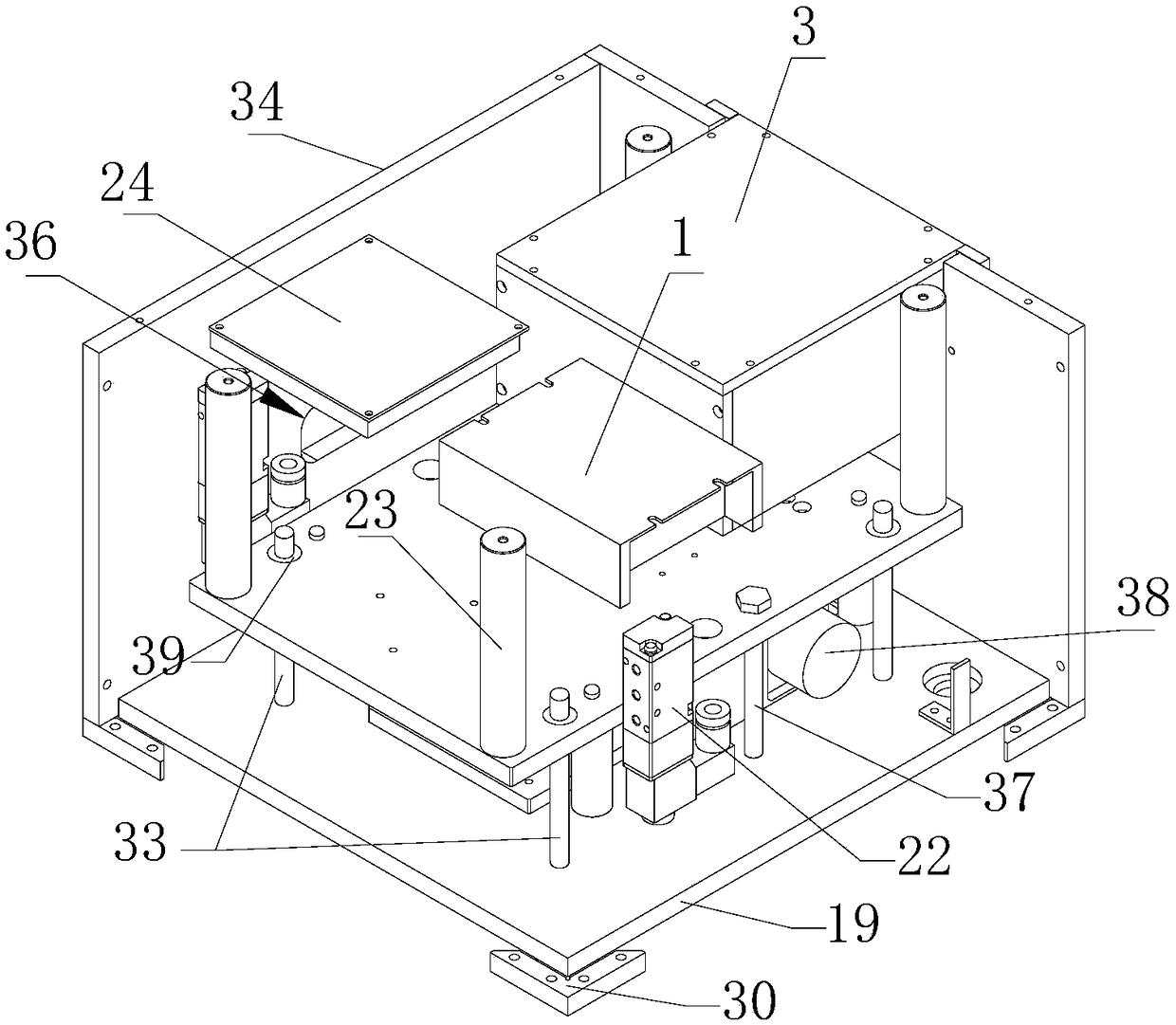
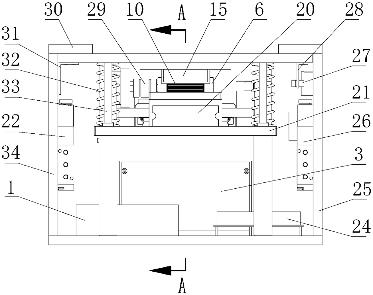
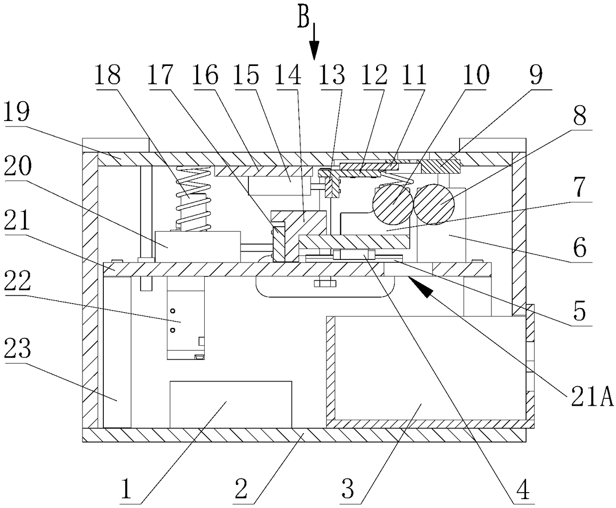
[0023] see figure 1 and Figure 4 , an automatic cutting machine for cable ties, comprising: a box body, a fixing plate, a tightening device, a shearing device and a control system.

[0024] The box body includes a bottom plate 2 and a cover plate 19 disposed opposite to the bottom plate 2. A first cable tie inlet 20A is defined on the cover plate 19, and a drawer box 3 for collecting waste is also arranged in the box body. , a power module 1 , which is installed on the base plate 2 to supply power to the device.

[0025] see figure 1 , figure 2 , image 3 and Figure 4 , the fixing plate 21 is arranged between the bottom plate 2 and the cover plate 19, and is installed on the four connecting rods 23 extending upward from the bottom plate 2, and the drawer box 3 is arranged on the bottom plate 2 and the Between the fixin...


PUM


Abstract

The invention relates to the field of banding strap cutting devices and discloses a banding strap automatic cutting machine in order to overcome the defects that the tensioning intensity of manual banding of plastic banding strap bundles is inconsistent and the working efficiency of manual cutting is low. The banding strap automatic cutting machine comprises a box, a fixed plate, a tensioning device, a cutting device and a control system, wherein the box comprises a bottom plate and a cover plate; the fixed plate is arranged between the bottom plate and the cover plate; the tensioning device comprises a driven roller, a driving roller, a first moving block and a first cylinder; the cylinder drives the driving roller on the first moving block to abut against the driven roller to tension banding straps; the cutting device used for cutting off the remaining parts of the tensioned banding straps and comprises a second cylinder, a second moving block, a cutter and a cutter holder; the second cylinder drives the cuter to slide on the cutter holder; the control device controls the tensioning device and the cutting device to act. The banding strap tensioning intensity of the banding strapautomatic cutting machine can be adjusted, and the banding strap automatic cutting machine can automatically cut off the banding straps after achieving the preset tensioning intensity.

Description

technical field [0001] The invention relates to the field of cable tie cutting devices, in particular to an automatic cable tie cutting machine. Background technique [0002] Cable ties, also known as cable ties, cable ties, and lock straps, as the name suggests, are straps for bundling things. The design has no stopping function, and can only be tightened more tightly. There are also detachable cable ties. Divided into metal ties, which are generally stainless steel materials and plastic ties, which are generally nylon materials, and are often used in cables for mechanical and electrical products, computers, electronic products, and automotive wiring harnesses. [0003] When bundling the wire harness, the plastic cable ties mainly rely on manual bundling and tightening, and then manually cut off the excess part of the cable tie, which has low work efficiency, and when bundling the wire harness, the strength of the bundling depends entirely on personal feelings, resulting in...

Claims


Application Information

Patent Timeline
Patent Type & Authority Applications(China)
IPC IPC(8): B65B13/22B65B13/18B65B61/06
CPCB65B13/18B65B13/22B65B61/06
Inventor 陈家全
Owner KATOLEC AUTOMOTIVE SYST GUANGZHOU CO LTD
Learn More