
Gap Adjustment Technology for Steel Beam Closing

A gap adjustment, steel beam technology, applied in bridges, bridge construction, erection/assembly of bridges, etc., can solve the problems of bridge alignment and internal force influence, large temperature influence, difficult to accurately control the amount of jacking, and achieve strong adaptability , the effect of high safety

Active Publication Date: 2020-09-01
CHINA COMM 2ND NAVIGATIONAL BUREAU 2ND ENG
View PDF9 Cites 0 Cited by
  • Summary
  • Abstract
  • Description
  • Claims
  • Application Information

AI Technical Summary

Problems solved by technology

In order to realize the closure of the steel structure, the following methods are generally adopted: 1. The overall push of the steel beam: use the jack to push the movable support to make the steel beam move as a whole and realize the adjustment of the longitudinal gap of the closing opening, which may cause the main beam to twist, and It is difficult to accurately control the amount of thrust; 2. Temperature matching and cutting: according to the needs, determine the length of the steel girder in the closing section, and carry out matching and cutting on site to realize the closing. 3. Chain hoists: Hang chain hoists at the ends of the chord rods on both sides of the closing mouth to adjust the longitudinal gap of the closing mouth. This method is not applicable when the mouth gap is small

Method used


Image

  • Gap Adjustment Technology for Steel Beam Closing
  • Gap Adjustment Technology for Steel Beam Closing
  • Gap Adjustment Technology for Steel Beam Closing

Examples


Embodiment 2

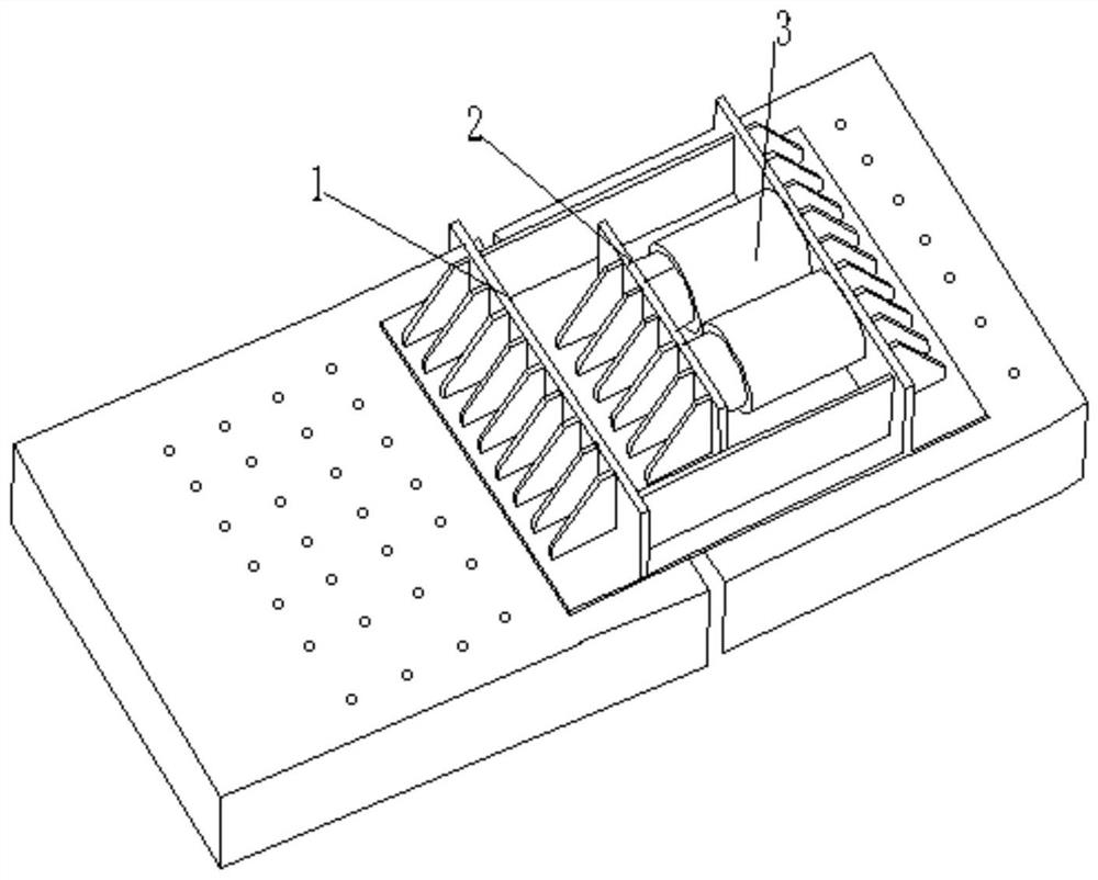
[0037] In Example 2, when the gap between the steel girders at the closing mouth is large and does not meet the design requirements, in order to ensure smooth closing, the gap between the steel girders needs to be adjusted smaller, such as figure 2 As shown, place the jack 3 at the position shown in the figure, and then start the jack 3.

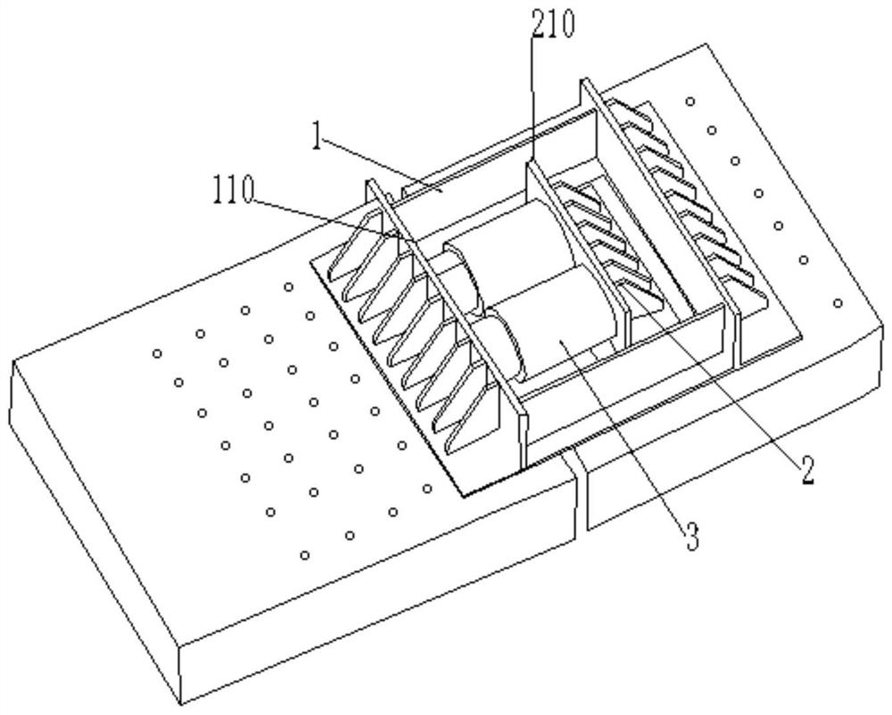
[0038] In another embodiment, such as figure 1 As shown, the A reaction force seat 1 has a frame structure, and the B reaction force seat 2 has a block structure; the A reaction force seat 1 has a square frame structure, and one end of the square frame structure extends outward to form a transverse diaphragm 110, when the A reaction force base 1 is laterally fixed on the steel beam, the a transverse diaphragm 110 is perpendicular to the surface of the steel beam, and is used to offset one end of the jack; one end of the B reaction force seat 2 faces The outer extension forms a b-diaphragm 210 , and when the B-reaction seat 2 is laterally f...


PUM


Abstract

The invention discloses a steel girder closure clearance adjusting process. The process comprises the following steps: step one: manufacturing a frame-shaped counterforce seat A and a blocky counterforce seat B; step two, horizontally fixing one end of the counterforce seat A on an upper surface of one of two to-be-adjusted steel girders, and freely locating the other end on the upper surface of the other steel girder; fixing the counterforce seat B on the other steel girder, and sleeving the counterforce seat B in the counterforce seat A; step three, erecting a jack in the counterforce seat A, wherein two ends of the of the jack are respectively propped against the inner side of one end of the counterforce seat A and the counterforce seat B; step four, starting the jack to push two steelgirders to move to the same direction or opposite directions, thereby adjusting the closure clearance of two steel girders until the closure clearance achieves the preset value. The construction method disclosed by the invention is convenient and fast, and high in safety; the steel girder closure distance adjusting can be quickly and conveniently realized; meanwhile, the construction method is strong in adaptation capacity and can be suitable for closure demands of all bolting structures.

Description

technical field [0001] The invention relates to the field of gap adjustment for steel beam closing. More specifically, the present invention relates to a process for adjusting the closing gap of steel beams. Background technique [0002] When the steel truss bridge is closed, it is necessary to adjust the closing gap vertically and accurately to ensure the installation accuracy of the closing section components. In order to realize the closure of the steel structure, the following methods are generally adopted: 1. The overall push of the steel beam: use the jack to push the movable support to make the steel beam move as a whole and realize the adjustment of the longitudinal gap of the closing opening, which may cause the main beam to twist, and It is difficult to accurately control the amount of thrust; 2. Temperature matching and cutting: according to the needs, determine the length of the steel girder in the closing section, and carry out matching and cutting on site to r...

Claims


Application Information

Patent Timeline
Patent Type & Authority Patents(China)
IPC IPC(8): E01D21/00
CPCE01D21/00
Inventor 刘小勇王元鑫范波许波吴鹏飞
Owner CHINA COMM 2ND NAVIGATIONAL BUREAU 2ND ENG
Learn More