
Cantilever structure with anti-collision and puncture functions

A technology of puncture needles and needle arms, which is applied in the field of accessories for testing equipment, and can solve the problem that the anti-collision strength of puncture needles cannot be adjusted.

Pending Publication Date: 2018-11-20
SICHUAN ORIENTER BIOLOGICAL TECH
View PDF0 Cites 0 Cited by
  • Summary
  • Abstract
  • Description
  • Claims
  • Application Information

AI Technical Summary

Problems solved by technology

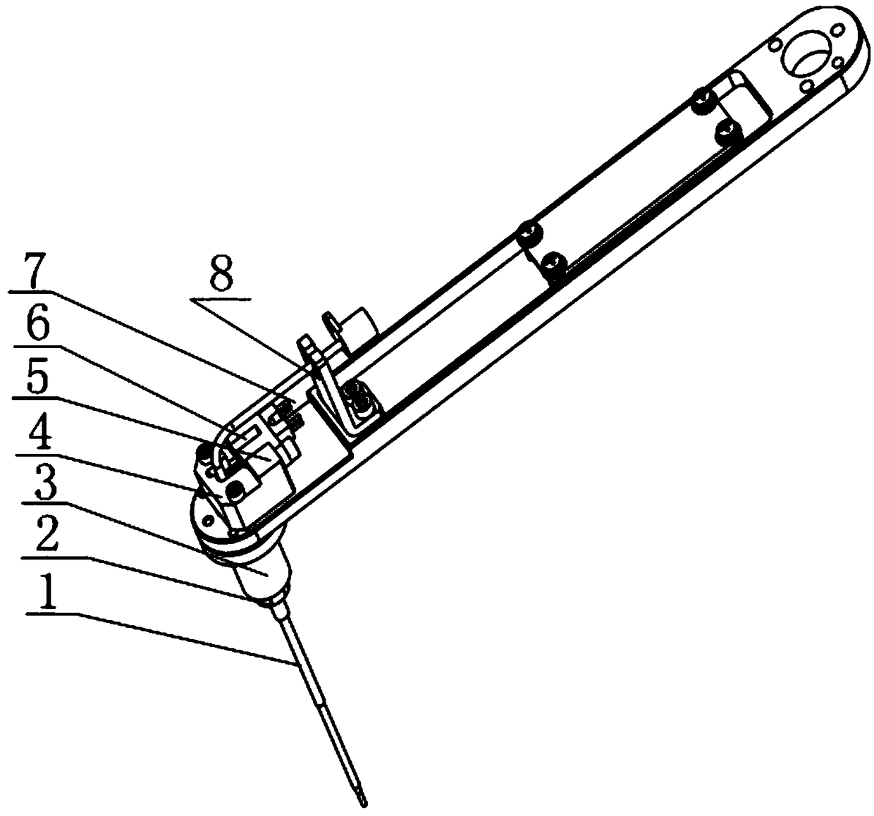
[0005] Aiming at one of the above-mentioned problems, the present invention provides a needle arm structure with an anti-collision puncture function, which uses a puncture needle that passes through the sensor fixing seat, support plate, guide sleeve, and limit post in sequence, and a needle arm is provided between the guide sleeve and the puncture needle. There is a cavity for the compression spring. During the movement of the needle arm, when the lower end of the puncture needle hits a hard object, the limit column moves upward together with the puncture needle to compress the spring until the needle sensing plate on the puncture needle blocks the photoelectric switch sensing area. , the movement of the needle arm stops, preventing the puncture needle from colliding, which solves the technical problems in the prior art that the anti-collision strength of the puncture needle cannot be adjusted, and the spring used cannot recover the direction of movement.

Method used


Image

  • Cantilever structure with anti-collision and puncture functions
  • Cantilever structure with anti-collision and puncture functions
  • Cantilever structure with anti-collision and puncture functions

Examples


Embodiment 1

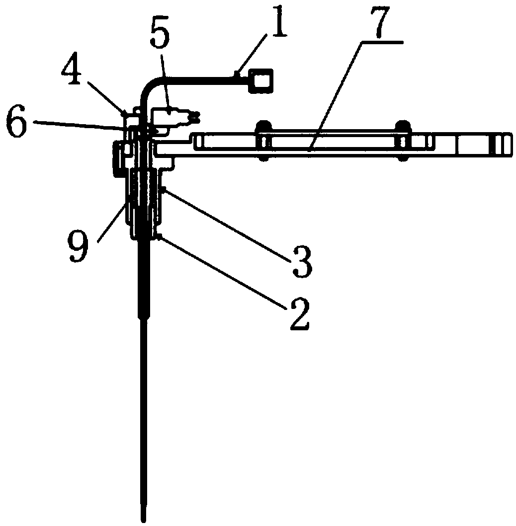
[0032] Such as figure 1 — Figure 8 As shown, a needle arm structure with anti-collision puncture function, including puncture needle 1, limit post 2, guide sleeve 3, sensor holder 4, photoelectric switch 5, needle induction sheet 6, compression spring 9, guide sleeve 3 Installed on the lower end of the sensor holder 4, the puncture needle 1 passes through the center of the sensor holder 4 and the guide sleeve 3 sequentially from top to bottom, a cavity is formed between the inner wall of the guide sleeve 3 and the outer wall of the puncture needle 1, and the compression spring 9 Set in the cavity, the limit column 2 is located at the lower end of the cavity and is detachably connected with the outer wall of the puncture needle 1, the limit column 2 can move upward together with the puncture needle 1 to compress the compression spring 9; the puncture needle 1 is provided with a needle The sensing sheet 6 and the needle sensing sheet 6 are located at the lower end of the photo...

Embodiment 2

[0043] The difference between this embodiment and Embodiment 1 is that the sensor fixing seat 4 is a block structure with a quadrilateral cross section, and the central area of ​​the sensor fixing seat 4 is provided with a through hole that facilitates the passage of the puncture needle 1, and the sensor is fixed Seat 4 is fixed with support plate 7 by bolt. The support plate 7 is located between the sensor fixing seat 4 and the guide sleeve 3 , and the support plate 7 is provided with a through hole 2 communicating with the through hole 1 . The second through hole on the support plate 7 communicates with the first through hole, the guide sleeve 3 and the limit post 2 to form a passage for the puncture needle 1 to pass through. The centerlines of the first through hole, the second through hole, the guide sleeve 3 and the limit post 2 coincide, that is, the center is on a straight line, which is convenient for the movement of the puncture needle 1 .

[0044] The concrete struc...

Embodiment 3

[0049] The difference between this embodiment and the above-mentioned embodiments is that there is a gap between the compression spring 9 and the puncture needle 1 . In this embodiment, the compression spring 9 is sheathed on the outer periphery of the puncture needle 1. The puncture needle 1 has a guiding effect on the compression spring 9, and can ensure that the rebound force of the compression spring 9 is always kept in the vertical direction without deflection. At the same time, the gap between the compression spring 9 and the puncture needle 1 can ensure that the normal compression of the compression spring 9 is not affected by the friction of the puncture needle 1 or the guide sleeve 3, avoiding the reduction and loss of the elastic force of the compression spring 9, and avoiding the occurrence of The compression spring and the matching parts are stuck and cannot be recovered.

[0050] In this embodiment, the optimization of the connection relationship between the compr...


PUM


Abstract

The invention discloses a cantilever structure with anti-collision and puncture functions, which comprises a puncture needle, a limit column, a guide sleeve, a sensor fixing seat, a photoelectric switch, a needle sensing piece and a pressure spring, wherein the guide sleeve is arranged at the lower end of the sensor fixing seat, the puncture needle sequentially runs through the centers of the sensor fixing seat and guide sleeve from top down, a cavity is formed between the inner wall of the guide sleeve and the outer wall of the puncture needle; the pressure spring is arranged in the cavity; the limit column is arranged at the lower end of the cavity and is in threaded connection with the outer wall of the puncture needle; the limit column can move up together with the puncture needle to compress the pressure spring, a needle sensing piece is arranged on the puncture needle, the needle sensing piece is arranged at the lower end of the photoelectric switch, the puncture needle moves upwards to the needle sensing piece to shield the sensing area of the photoelectric switch, and the cantilever stops moving. According to the technical scheme, the anti-collision strength of the punctureneedle can be adjusted by adjusting the force of the pressure spring, and meanwhile, the force of the pressure spring can also achieve a certain degree of puncture function.

Description

technical field [0001] The invention relates to the technical field of accessories for detection equipment, in particular to a needle arm structure with anti-collision puncture function. Background technique [0002] A cantilever needle structure is often used in the IVD industry, which is mostly used in biochemical analyzers, immunochemiluminescence and other types of detection instruments. The commonly used anti-collision structures are cantilever anti-collision supports or double spring anti-collision supports. The anti-collision prevents the needle from being bent by misoperation. When the needle is ejected or pushed into the pre-designed sensor detection range, it is judged whether the needle has collided. The commonly used cantilever anti-collision support uses only one spring and uses The force center of the cantilever structure is not at the axis of the needle, which may cause the needle to collide with uneven force, unable to return to the original position and stuc...

Claims


Application Information

Patent Timeline
IPC IPC(8): G01D11/00
CPCG01D11/00
Inventor 周杰
Owner SICHUAN ORIENTER BIOLOGICAL TECH
Learn More