
Cutting clamping mechanism and cutting system provided with same

A clamping mechanism and clamping technology, applied in the direction of manufacturing tools, grinding workpiece supports, grinding machines, etc., can solve the problems of small clamping force, uneven cutting surface, affecting cutting quality, etc., and achieve flexible use and balanced force Effect

Pending Publication Date: 2020-09-25
福建茂田科技有限公司
View PDF1 Cites 0 Cited by
  • Summary
  • Abstract
  • Description
  • Claims
  • Application Information

AI Technical Summary

Problems solved by technology

However, the grinding wheel exerts downward force on the thimble in the vertical direction, and the base will also generate an upward rebound force on the thimble. The traditional thimble fixture lacks the clamping force on the vertical direction of the thimble, or the vertical force on the thimble. The clamping force is too small, which makes the thimble jump in the vertical direction during the cutting process, resulting in uneven cutting surface and affecting the cutting quality

Method used


Image

  • Cutting clamping mechanism and cutting system provided with same
  • Cutting clamping mechanism and cutting system provided with same
  • Cutting clamping mechanism and cutting system provided with same

Examples


Embodiment Construction

[0027] In order to further explain the technical solution of the present invention, the present invention will be described in detail below through specific examples.

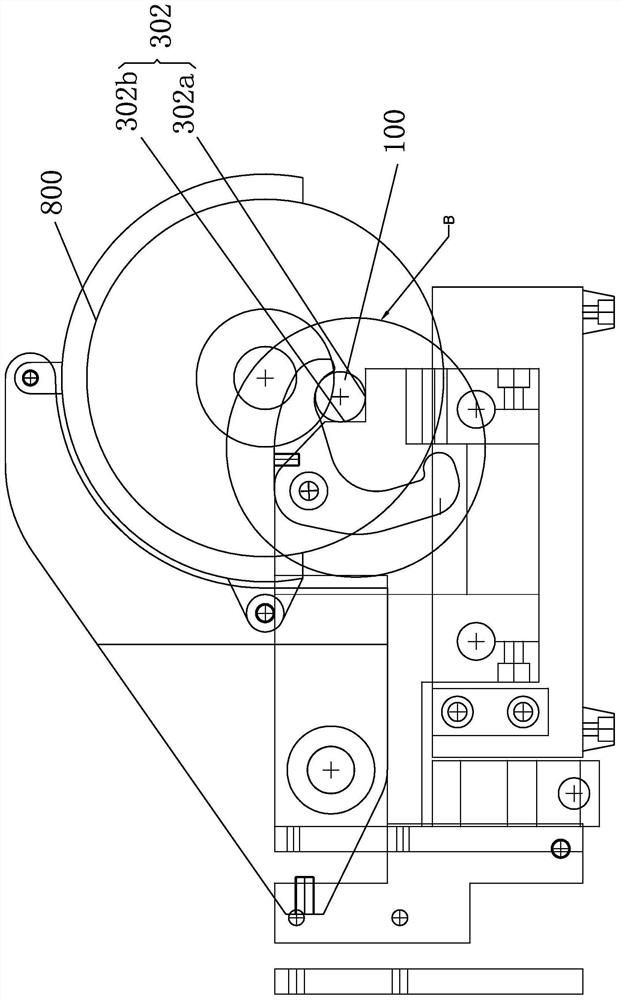
[0028] Such as Figure 1-6 As shown, this case provides a cutting and clamping mechanism for cutting a thimble 100. The thimble 100 includes an adjusting end 101 and a cutting end 102. The adjusting end 101 is moved to adjust the length of the thimble 100, and the thimble 100 meeting the length requirement is cut.

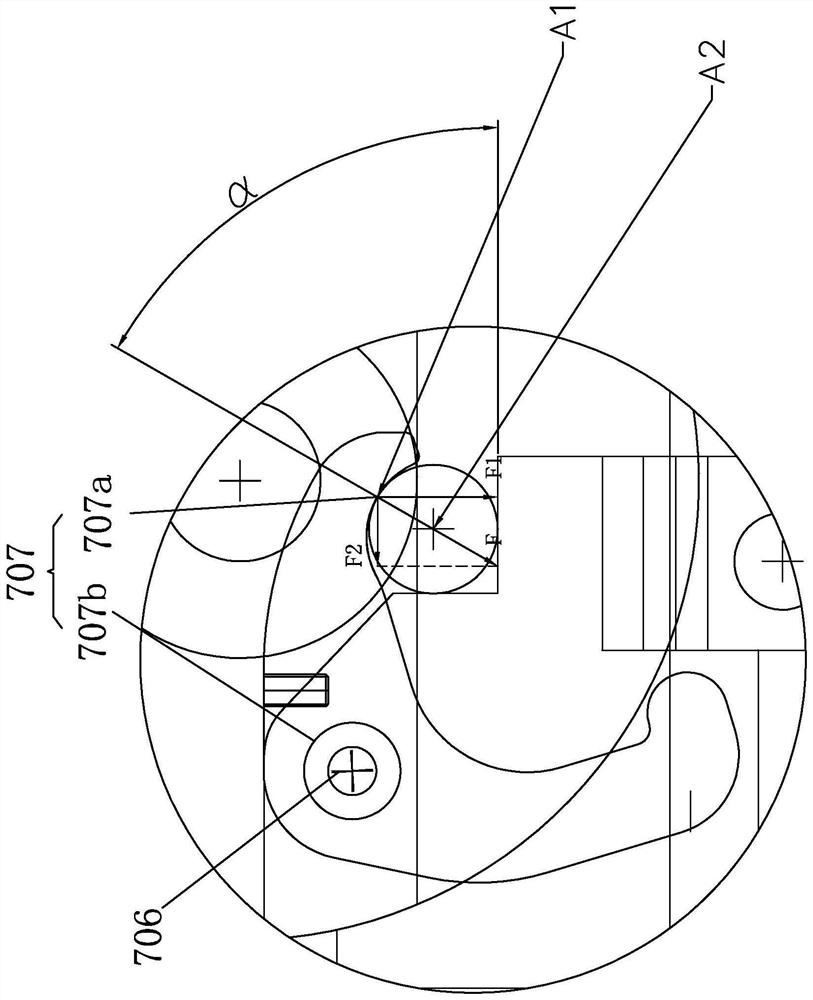
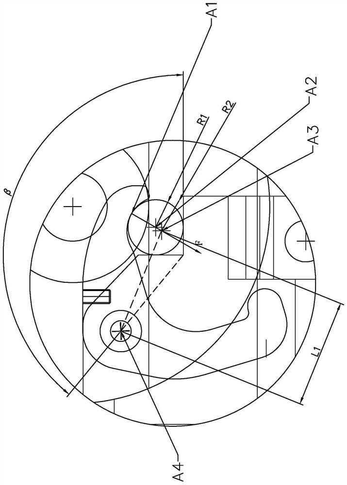
[0029] The cutting and clamping mechanism includes a cutting assembly 800 , a clamping platform 302 , a rotating shaft 706 and a clamping hook 707 . The clamping platform 302 includes a first platform 302a and a second platform 302b. The cutting end 102 of the thimble 100 is clamped on the clamping platform 302 and is tangent to the first platform 302a and the second platform 302b. The clamping platform 302 is opposite to the thimble 100 A rebound force is generated, and the center of the cross-sec...


PUM


Abstract

The invention discloses a cutting clamping mechanism which is used for cutting an ejector pin. The ejector pin comprises an adjusting end and a cutting end; the cutting clamping mechanism comprises acutting component, a clamping table, a rotary shaft and a clamping hook; the clamping table comprises a first table top and a second table top; the ejector pin is clamped on the clamping table and istangent with the first table top and the second table top; the clamping hook comprises a rotating hole and a clamping cambered surface part tangent with the ejector pin; the clamping cambered surfacepart is propped against the ejector pin and generates the vertical pressure F1 and the horizontal pressure F2 to the ejector pin; and the rotating hole is rotatably formed in the rotary shaft in a sleeving manner and does spin motion around the rotary shaft to enable the vertical pressure F1 to be greater than the horizontal pressure F2. According to the scheme, the propping and jacking resultantforce F acts on the ejector pin and can be divided into the vertical pressure and the horizontal pressure, and the vertical pressure is greater than the horizontal pressure, so that the acting force of a grinding wheel to the ejector pin is ensured to be counteracted, the ejector pin is stressed in balance during the cutting process, and the ejector pin does not move in the horizontal direction orjumps in the vertical direction.

Description

technical field [0001] The invention relates to the technical field of thimble processing, in particular to a cutting clamping mechanism and a cutting system with the clamping mechanism. Background technique [0002] Ejector pin is a kind of mold accessories, also called push rod, center pin and support pin, usually used to eject products formed in the mold, including countersunk head and cylinder, when using with the mold, it needs to carry out necessary adjustments according to the product requirements. Processing, wherein the length processing of the cylinder is indispensable, the length processing is mainly processed by a thimble cutting machine, the traditional cutting machine structure is known, such as a thimble jig disclosed in the Chinese invention patent with application number 201310155040.9, including Base, several clamping parts, cylinder and positioning backing plate, the base is provided with a fixing part, the several clamping parts are installed on one side ...

Claims


Application Information

Patent Timeline
Patent Type & Authority Applications(China)
IPC IPC(8): B24B27/06B24B41/06
CPCB24B27/06B24B41/06
Inventor 黄少杰黄司弘
Owner 福建茂田科技有限公司
Learn More