
Frequency domain reverse time migration algorithm based on layered medium Green's function

A technology of Green's function and layered media, which is applied to the re-radiation of sound waves, the reflection/re-radiation of radio waves, and instruments, etc., which can solve the problems of limited engineering applications, high computational cost of time-domain reverse time migration algorithm, and incapable of real-time data Dealing with and other issues to achieve the effect of saving computing costs

Active Publication Date: 2018-11-20
GUANGZHOU UNIVERSITY
View PDF4 Cites 6 Cited by
  • Summary
  • Abstract
  • Description
  • Claims
  • Application Information

AI Technical Summary

Problems solved by technology

Due to the need to perform reverse time migration calculation processing for each shot or each transmitting antenna position, the calculation cost of the time domain reverse time migration algorithm is very large, which limits its engineering application
In recent years, with the development of geophysical instruments such as ground penetrating radar, the data acquisition speed is often very fast in some engineering applications, and a large amount of data can be obtained quickly. Therefore, the traditional time domain reverse time migration algorithm cannot perform real-time data processing Handle and guide on-site operations

Method used


Image

  • Frequency domain reverse time migration algorithm based on layered medium Green's function
  • Frequency domain reverse time migration algorithm based on layered medium Green's function
  • Frequency domain reverse time migration algorithm based on layered medium Green's function

Examples


Embodiment

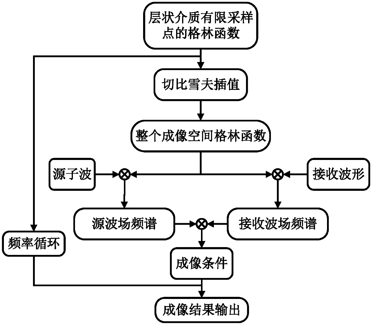
[0032] Such as figure 1 As shown, in this embodiment, a frequency domain reverse time migration algorithm based on layered medium Green's function includes the following steps:

[0033] Step 1. First calculate the dyadic Green's function of the diagonal sampling points in the layered medium space within the effective frequency band, and obtain the Green's function of the entire imaging space through Chebyshev interpolation. Taking the electromagnetic field as an example, the specific steps to calculate the dyadic Green's function of the diagonal sampling point in the layered medium space are as follows:

[0034] Set the propagation direction of the wave as z, since the transverse medium perpendicular to z is uniform and infinitely extended, calculate the electric field type Green's function of the electric field E generated by the current source J

[0035]

[0036] The unit vector (u, v) in formula (1) is the rotation coordinate vector defined in the spectrum domain, and...


PUM


Abstract

The invention discloses a frequency domain reverse time migration algorithm based on the layered medium Green's function. The method comprises steps that S1, the dyadic Green's function of diagonal sampling points of the layered medium space is calculated within the effective frequency band range, and the Green's function of the entire imaging space is obtained through Chebyshev interpolation; S2,the spectrum of data recorded by a receiver after source spectrum or inverse time processing is respectively multiplied by the Green's function of the imaging space, and the forward extension wave field and the reverse extension wave field of the entire imaging space are calculated; and S3, the forward extension wave field and the reverse extension wave field are multiplied according to the cross-correlation imaging condition of the frequency domain, stepping calculation of wave field products of all the sampling frequency points in the effective frequency band range is performed, accumulation is further performed, and the sum after accumulation is subjected to Laplacian filtering and is then taken as the inverse time migration imaging result of the imaging space. The method is advantagedin that the imaging points at the same horizontal plane within the imaging space only require one-time calculation of the Green's function, so calculation cost is greatly saved, and high precision imaging of the underground medium can be quickly performed.

Description

technical field [0001] The invention belongs to the technical field of near-surface non-destructive detection, and in particular relates to a frequency domain reverse time migration algorithm based on layered medium Green's function. Background technique [0002] Near-surface exploration uses geophysical methods to obtain the structure of the subsurface medium and the location of targets. These geophysical prospecting methods include ground penetrating radar, shallow seismic prospecting and ultrasonic sounding, etc., and the processing and migration imaging of the detected data is the key to its correct interpretation. The reverse time migration algorithm has high precision and has obvious advantages in dealing with complex velocity models and steep slope structures, and has developed into one of the mainstream methods for processing these geophysical data. [0003] Traditional RTM algorithms use finite-difference time-domain methods to compute the wavefields of electromagn...

Claims


Application Information

Patent Timeline
IPC IPC(8): G01S13/89G01S15/89
CPCG01S13/89G01S15/89
Inventor 刘海林春旭齐橼崔杰刘超
Owner GUANGZHOU UNIVERSITY
Learn More