Solar charging seat

A technology of solar energy and charging sockets, which is applied to vertically adjustable chairs, chairs, collectors, etc., can solve the problem that the seats do not have solar charging services, and achieve the effect of convenient travel and convenient life

Pending Publication Date: 2018-11-23
SICHUAN JIANYUAN ENERGY SAVING TECH CO LTD
View PDF1 Cites 0 Cited by
  • Summary
  • Abstract
  • Description
  • Claims
  • Application Information

AI Technical Summary

Problems solved by technology

[0004] The purpose of the present invention is to provide a solar charging seat to solve the problem that the existing seats do not have the ability to use solar energy to provide charging services for people

Method used


Image

  • Solar charging seat
  • Solar charging seat

Examples


specific Embodiment 1

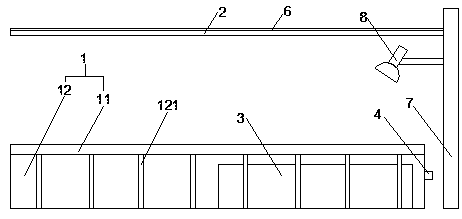
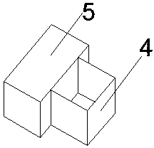
[0024] figure 1 , figure 2 A solar charging seat is shown, including a seat 1 and a sunshade 2, the seat 1 includes a seat surface 11 and a storage box 12 arranged in sequence from top to bottom, and a storage battery 3 is arranged in the storage box 12 , the middle part of the outer wall of the storage box 12 is provided with a groove, and the two inner sides of the notch of the groove are provided with limit stops, and a drawer box 4 is arranged in the groove, and the width of the drawer box 4 is the same as that of the two limit stoppers. The spacing between the bars is the same, and the end of the drawer box 4 located in the groove is provided with a limit block 5, the width of the limit block 5 is greater than the distance between the two limit bars, and the drawer box 4 is equipped with a charging socket. The input end of the charging socket is electrically connected to the output end of the storage battery 3, the awning 2 is arranged above the seat 1, the top of the a...

specific Embodiment 2

[0026] This embodiment is based on the specific embodiment 1 to further illustrate the connection method between the sunshade 2 and the ground, and the bottom of one side of the sunshade 2 is connected to the ground through the support rod 7 .

specific Embodiment 3

[0027] In this embodiment, an LED lamp 8 is added on the basis of the specific embodiment 2. The middle part of the support rod 7 is provided with an LED lamp 8. The support rod 7 is a hollow structure, and the wires of the LED lamp 8 pass through the hollow of the support rod 7. The cavity is electrically connected to the battery (3), the switch of the LED lamp 8 is arranged at the lower part of the support rod 7, and the switch of the LED lamp 8 is 1-1.2m away from the ground.

[0028] Set up LED lights, and the LEDs are electrically connected to the battery. At night, turning on the LED lights can provide lighting services for people who are resting. Set the switch of the LED lights at a distance of 1-1.2m from the ground, so that the LED lights can It is more convenient to open and close, and it is not convenient for people to press the switch if it is too high or too low.


PUM


Abstract

The invention discloses a solar charging seat. The solar charging seat comprises a seat and an awning, wherein the seat comprises a seat surface and a storage box which are arranged from top to bottomin sequence; a storage battery is arranged in the storage box; a groove is formed in the middle part of the outer side wall of the storage box; limit barrier strips are arranged in two inner sides ofan opening of the groove; a drawable box is arranged in the groove; the width of the drawable box is as same as spacing between the two limit barrier strips; a limit block is arranged at one end, positioned in the groove of the drawable box; the width of the limit block is greater than the spacing between the two limit barrier strips; a charging socket is mounted in the drawable box; the input end of the charging socket is electrically connected with the output end of the storage battery; the awning is arranged above the seat; a solar panel is arranged at the top of the awning; the output endof the solar panel is electrically connected with the input end of the storage battery. Through the solar charging seat, the problem that the existing seat is incapable of providing charging servicefor people by using solar energy is solved.

Description

technical field [0001] The invention relates to the field of solar energy equipment, in particular to a solar charging seat. Background technique [0002] With the development of society, people pay more and more attention to the use of clean energy, because clean is not only pollution-free, but also a renewable energy, which is very important for the protection of the earth's ecology. Solar energy is the most widely used clean energy. energy. [0003] The seats on the existing streets are usually only for people to rest, and do not have the function of sunshade. At the same time, the seats on the existing streets are usually not equipped with solar energy devices and charging mechanisms, which cannot provide charging for people resting on the seats. Serve. Contents of the invention [0004] The purpose of the present invention is to provide a solar charging seat to solve the problem that the existing seats do not have the ability to use solar energy to provide charg...

Claims


Application Information

Patent Timeline
Patent Type & Authority Applications(China)
IPC IPC(8): A47C3/00A47C7/24A47C7/72H02J7/35
CPCA47C3/00A47C7/24A47C7/72H02J7/35
Inventor 徐斌斌
Owner SICHUAN JIANYUAN ENERGY SAVING TECH CO LTD
Why Eureka
Try Eureka