Logistic packing case fixing mechanism
A technology for fixing mechanism and cargo box, which is applied in positioning devices, metal processing equipment, feeding devices, etc., can solve the problems of inability to adjust the clamping direction, and can not realize the clamping of logistics cargo boxes in multiple directions, and achieve fast installation. and the effect of disassembly
- Summary
- Abstract
- Description
- Claims
- Application Information
AI Technical Summary
Problems solved by technology
Method used
Image

Examples
specific Embodiment approach 1
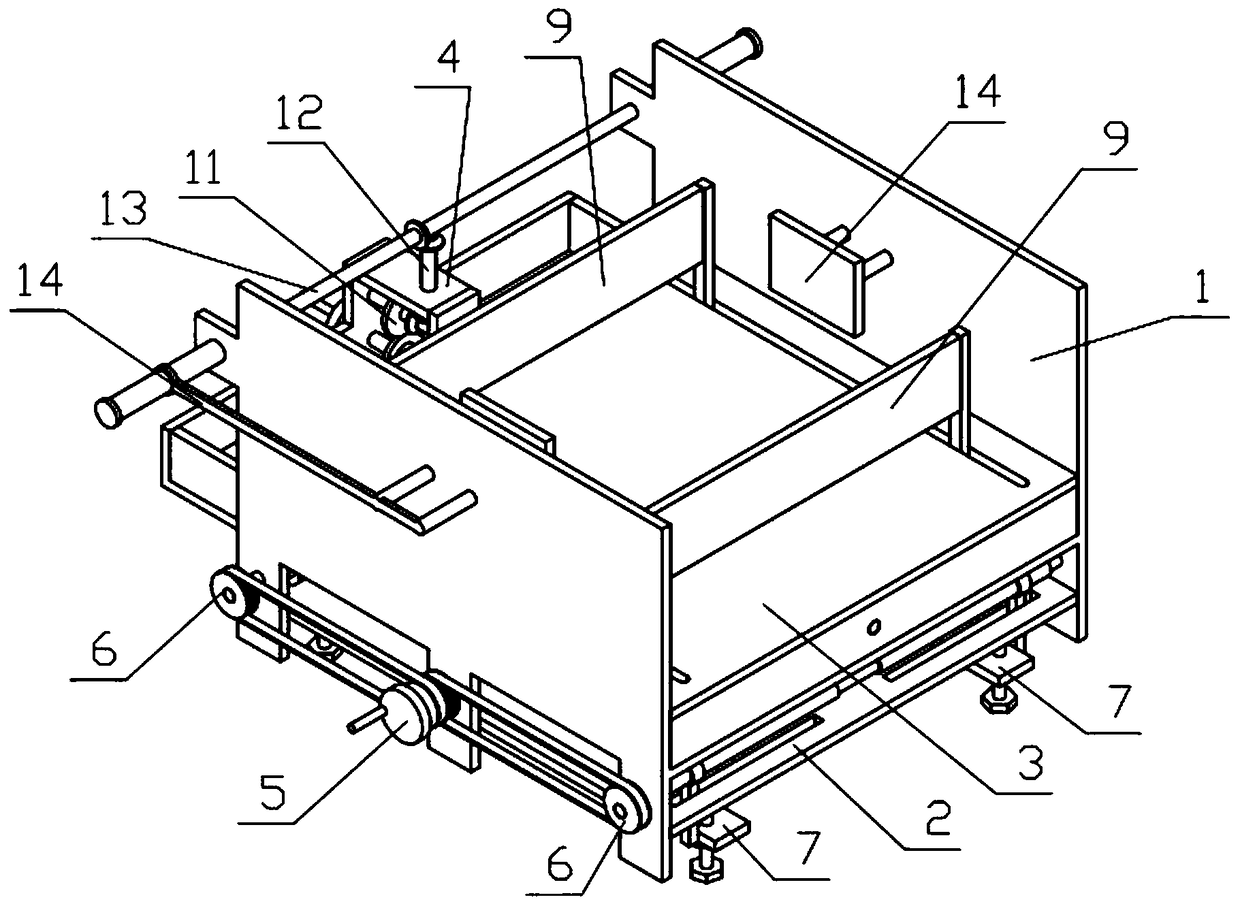
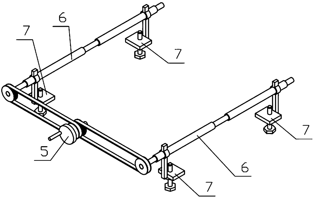
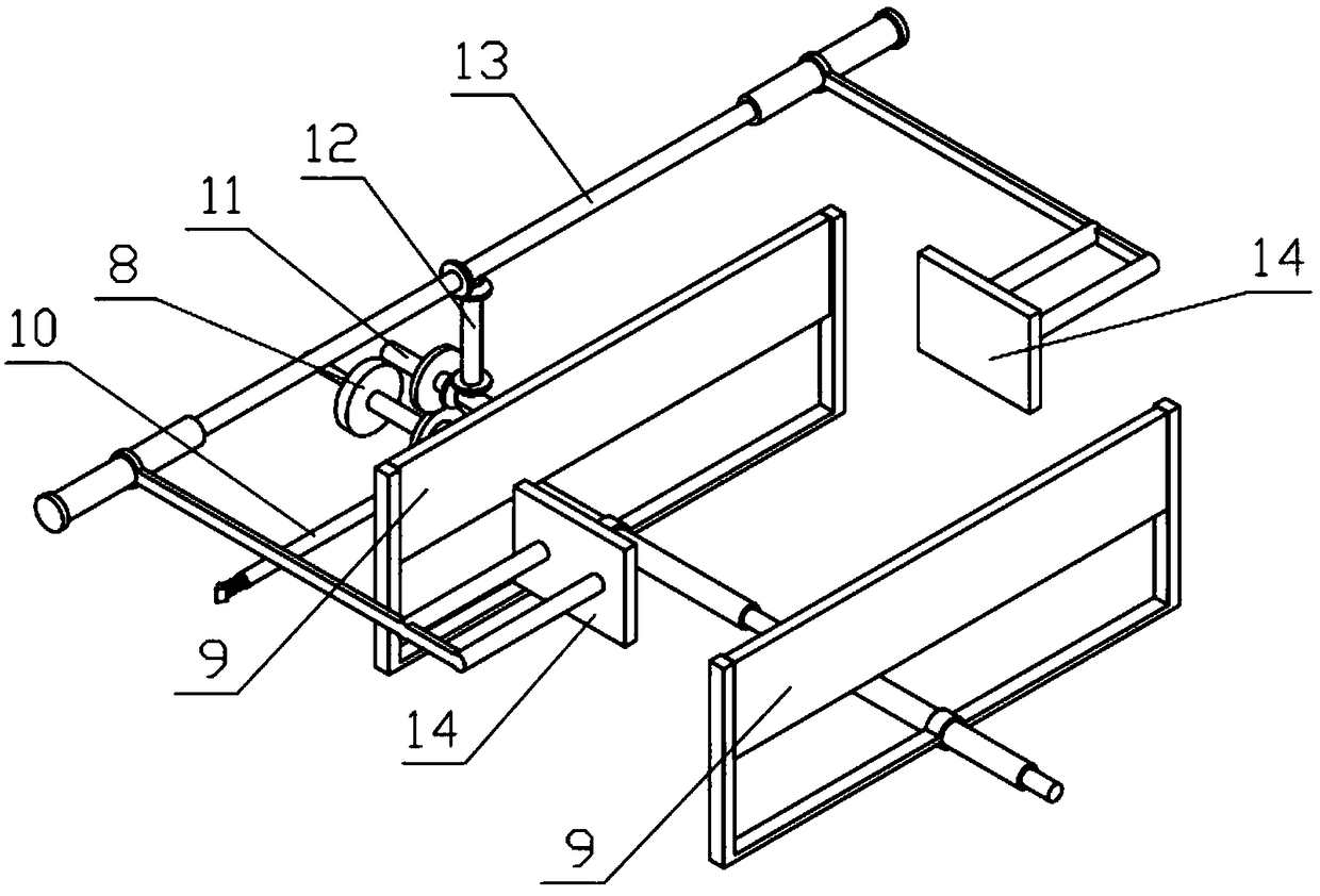
[0046] Combine below Figure 1-21 Describe this embodiment, a logistics container fixing mechanism, including the whole machine bracket 1, the sliding bottom plate 2, the sliding upper plate 3, the rotating support plate 4, the installation power mechanism 5, the installation transmission mechanism 6, the installation mechanism 7, the clamping power Mechanism 8, left and right clamping hands 9, control mechanism 10, transmission mechanism 11, direction changing mechanism 12, clamping transmission mechanism 13 and front and rear clamping hands 14, the sliding bottom plate 2 is fixedly connected to the whole machine support 1, The sliding upper plate 3 is fixedly connected to the whole machine support 1, the rotating support plate 4 is fixedly connected to the whole machine support 1, the installation power mechanism 5 is rotatably connected to the whole machine support 1, and two installation transmission mechanisms 6 are symmetrically arranged on the left and right sides. The ...
specific Embodiment approach 2
[0047] Combine below Figure 1-21 Describe this embodiment, this embodiment will further explain the first embodiment, the whole machine bracket 1 includes a bottom plate 1-1, side plates 1-2, linear bearing holes 1-3, left and right side plates 1-4, front and rear side plates 1-5, left and right sliding grooves Ⅰ1-6, W-shaped clamping body 1-7, left end baffle 1-8 and front and rear sliding grooves Ⅰ1-9, two side plates 1-2 are symmetrically arranged front and back, two side plates The middle ends of 1-2 are respectively fixedly connected to the front and rear ends of the bottom plate 1-1, four linear bearing holes 1-3 are provided, and the four linear bearing holes 1-3 are respectively arranged on the two side plates 1-2, There are two left and right side plates 1-4 symmetrically arranged, and the lower ends of the two left and right side plates 1-4 are respectively fixedly connected to the left and right ends of the base plate 1-1, and there are two front and rear side plat...
specific Embodiment approach 3
[0048] Combine below Figure 1-21 This embodiment will be described. This embodiment will further explain the second embodiment. Four front and rear sliding grooves II2-1 are symmetrically arranged on the sliding bottom plate 2, and the two ends of the sliding bottom plate 2 are fixedly connected to the two side plates 1 respectively. -2 up;
[0049] The sliding upper plate 3 includes a sliding upper plate body 3-1, a rotating plate 3-2 and a left and right sliding groove II 3-3, the lower end of the rotating plate 3-2 is fixedly connected to the left end of the sliding upper plate body 3-1, and slides left and right. There are two grooves II 3-3 symmetrically arranged front and back, and the two left and right sliding grooves II 3-3 are both arranged on the sliding upper plate body 3-1, and the left and right ends of the sliding upper plate body 3-1 are fixedly connected to the two left and right sides respectively. the upper end of plates 1-4;
[0050] The left and right e...
PUM
 Abstract
Description
Claims
Application Information
 - R&D Engineer
- R&D Manager
- IP Professional
- Industry Leading Data Capabilities
- Powerful AI technology
- Patent DNA Extraction
Browse by: Latest US Patents, China's latest patents, Technical Efficacy Thesaurus, Application Domain, Technology Topic.
© 2024 PatSnap. All rights reserved.Legal|Privacy policy|Modern Slavery Act Transparency Statement|Sitemap