
A control device, system, method and device for automatically adjusting the pretightening force of a spindle shaft system

An automatic adjustment and pre-tightening technology, applied in manufacturing tools, metal processing equipment, metal processing machinery parts, etc., can solve the problem of inability to automatically adjust the pre-tightening force of the spindle shaft system

Active Publication Date: 2021-05-25
GUANGZHOU HAOZHI ELECTROMECHANICAL
View PDF0 Cites 0 Cited by
  • Summary
  • Abstract
  • Description
  • Claims
  • Application Information

AI Technical Summary

Problems solved by technology

[0006] In order to overcome the deficiencies of the prior art, one of the objectives of the present invention is to provide a control device for automatically adjusting the pretightening force of the spindle shaft system, which can solve the problem that the existing lathe processing cannot automatically adjust the spindle shaft system according to the type of plate to be processed. preload problem
[0007] The second object of the present invention is to provide a control system for automatically adjusting the preload of the spindle shaft system, which can solve the problem that the existing lathe processing cannot automatically adjust the preload of the spindle shaft system according to the type of plate to be processed
[0008] The third object of the present invention is to provide a control method for automatically adjusting the pretightening force of the spindle shaft system, which can solve the problem that the existing lathe processing cannot automatically adjust the pretightening force of the spindle shaft system according to the type of plate to be processed

Method used


Image

  • A control device, system, method and device for automatically adjusting the pretightening force of a spindle shaft system
  • A control device, system, method and device for automatically adjusting the pretightening force of a spindle shaft system

Examples


Embodiment Construction

[0033] Below, the present invention will be further described in conjunction with the accompanying drawings and specific implementation methods. It should be noted that, under the premise of not conflicting, the various embodiments described below or the technical features can be combined arbitrarily to form new embodiments. .

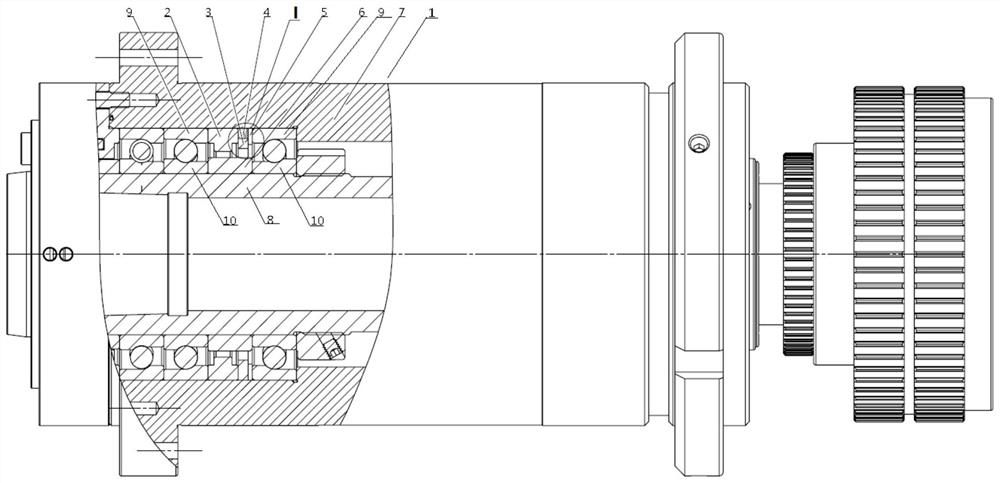
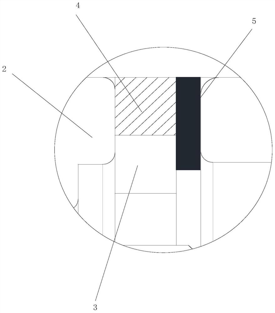
[0034] like figure 1 and 2 As shown, in order to solve the above defects, the present invention provides a control device for automatically adjusting the pretightening force of the main shaft bearing, which includes the shaft core 8 installed on the lathe assembly 1, the body 7 and the main shaft bearing. Wherein, the bearing is sleeved on the outside of the shaft core 8, and the body 7 is sleeved on the outside of the bearing. The bearing generally includes a bearing outer ring 10 and a bearing inner ring 9, since the bearing outer ring 10 is floating relative to the bearing inner ring 9 without preload. Generally speaking, the purpose of changing ...


PUM


Abstract

The invention discloses a control device for automatically adjusting the pretightening force of a main shaft shaft system, which is provided by installing an outer ring spacer assembly and an inner ring spacer between two adjacent bearings along the axial direction of the main shaft core , the outer ring spacer assembly includes a piezoelectric ceramic spacer, a displacement sensor, an outer ring spacer, and a pressure sensor. By changing the deformation of the piezoelectric ceramic spacer, the height of the outer ring spacer assembly is changed, thereby changing the outer ring spacer. The height difference between the sleeve assembly and the inner and outer spacers in the axial direction changes the interaction force between the outer ring of the bearing and the inner ring of the bearing, that is, the preload of the spindle bearing, and realizes the flexibility of the preload of the spindle bearing. Adjustment can match the lathe processing with the type of parts, and realize the targeted processing of parts. The invention also provides corresponding control system, method, electronic equipment and storage medium.

Description

technical field [0001] The invention relates to the field of automatic lathe processing, in particular to a lathe spindle system device installed on the lathe field. Background technique [0002] At present, when a workshop master uses a lathe to turn a part, he first needs to determine the hardness of the part being processed, because parts with different hardness require different optimum processing speeds and rigidities of the lathe, such as steel, copper, Aluminum parts and other parts with different hardness. The stiffness of the lathe spindle is directly determined by the preload of the spindle bearing. When processing different types of parts, in order to give full play to the best working performance of the lathe spindle, it is necessary to flexibly adjust the preload of the spindle bearing to meet the requirements of different types of parts and the preload of the lathe spindle shaft system. The contradictory relationship between the load and the maximum working l...

Claims


Application Information

Patent Timeline
Patent Type & Authority Patents(China)
IPC IPC(8): B23B19/02
CPCB23Q1/70
Inventor 汤秀清刘贝加
Owner GUANGZHOU HAOZHI ELECTROMECHANICAL
Learn More