
A welding and clamping device for multi-bent pipe fittings and brackets

A technology of welding clamps and pipe bends, which is applied in welding equipment, auxiliary devices, welding accessories, etc., can solve the problems of inaccurate alignment and welding, inaccurate alignment, prone to rolling, shaking and movement, etc., and achieve stable position , Precise positioning and locking effect

Active Publication Date: 2019-04-30
GUANGDONG JUNCHI TECH HLDG
View PDF7 Cites 0 Cited by
  • Summary
  • Abstract
  • Description
  • Claims
  • Application Information

AI Technical Summary

Problems solved by technology

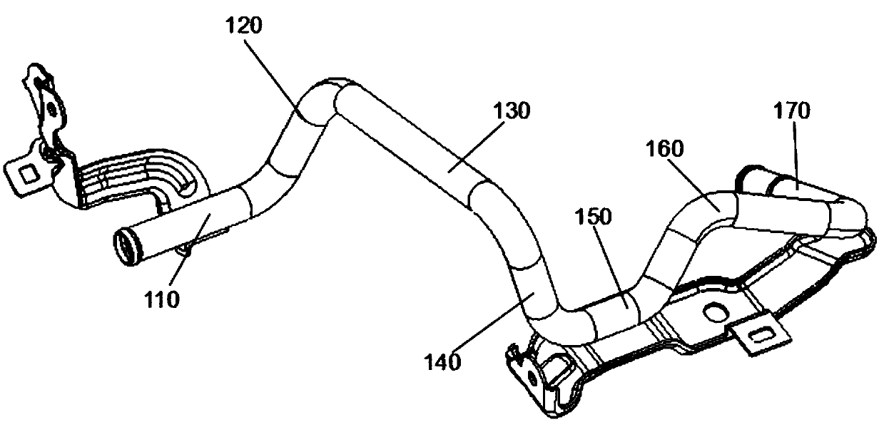
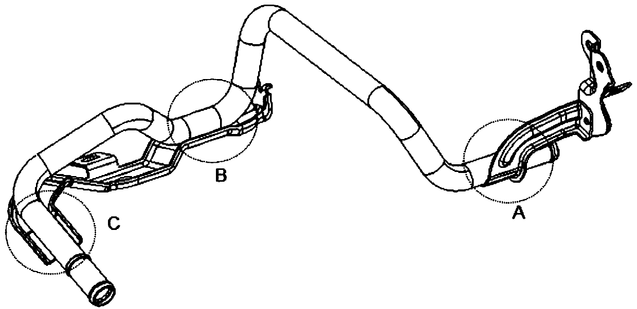
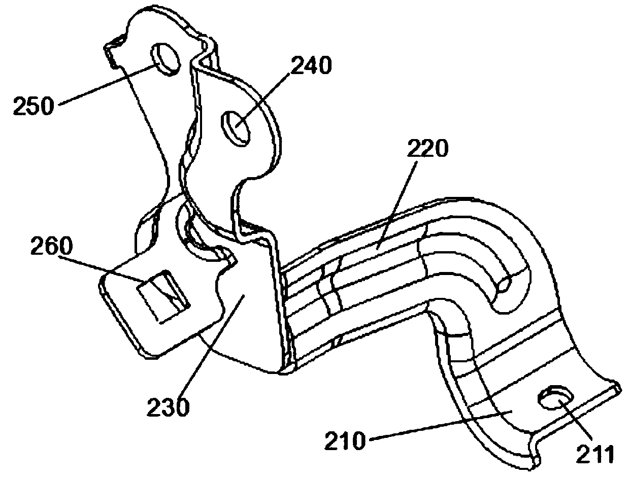
[0003] Since the oil cooling pipe 100 is a precision core component of the engine, the accuracy of installation is particularly important, so high requirements are placed on the welding accuracy of the left bracket 200 and the right bracket 300, and the processing of the actual workpiece requires the left bracket 200 and the right bracket 300. After being welded with the oil cooling pipe 100, the two nozzle end faces and their centerline positions are related to the first installation hole 240 and the second installation hole 250 on the left bracket 200, the third installation hole 321 and the fourth installation hole on the right bracket 300. The relative position change between the mounting holes 341 is less than 0.5mm, and the welding of the left bracket 200 and the right bracket 300 and the oil cooling pipe 100 needs to be accurately aligned at least three places (refer to Figure 4 As shown), at the same time, because the oil cooling pipe 100 is a special-shaped round pipe, it is difficult to fix, and it is prone to roll, shake and move during the specific welding process, which can easily cause inaccurate alignment and welding. The left bracket 200 and the right bracket 300 They are also special-shaped parts, which are difficult to fix, and are prone to inaccurate alignment during welding, which will affect the welding quality

Method used


Image

  • A welding and clamping device for multi-bent pipe fittings and brackets
  • A welding and clamping device for multi-bent pipe fittings and brackets
  • A welding and clamping device for multi-bent pipe fittings and brackets

Examples


Embodiment

[0035] Embodiment: A welding and clamping device for multi-bending pipe fittings and brackets.

[0036] refer to Figure 1 to Figure 14 As shown, a welding clamping device for multi-bending pipe fittings and brackets, including:

[0037] Fixture bottom plate 1; the first elbow positioning seat 11 fixed on the middle part of the fixture bottom plate 1 by screws, the rear end of the left side, the top and the front end of the right side of the first elbow positioning seat 11 are respectively provided with oil circuit cooling In the pipe 100, the left connecting elbow portion 120, the middle horizontal straight pipe portion 130, and the middle connecting elbow portion 140 match the positioning groove, and the first quick clip 12 is installed on the right side wall of the first elbow positioning seat 11, so that The first quick clamp 12 and the positioning groove on the first elbow positioning seat 11 constitute the first clamping position for the oil cooling pipe 100, and the fi...


PUM


Abstract

The invention provides a multiple-bend pipe fitting and support welding and clamping device. The multiple-bend pipe fitting and support welding and clamping device comprises a clamp baseplate, a firstbent pipe positioning seat arranged at the middle part of the clamp baseplate, a left support convex piece arranged at the left side of the first bent pipe positioning seat, a left support positioning seat arranged at the rear of the left support convex piece, a first rapid positioning clamp and a second rapid positioning clamp fixed on the front side surface of a first positioning clamp installing seat, a right support positioning seat arranged on the front side of the first bent pipe positioning seat, a right support positioning clamp arranged at the left side of the right support positioning seat, and a second bent pipe positioning seat arranged at the rear of the first right support convex piece. The multiple-bend pipe fitting and support welding and clamping device can realize the rapid positioning and clamping among a multiple-bend oil line cooling pipe, a left support and a right support, prevents the multiple-bend oil line cooling pipe, the left support and the right support from rolling, shaking or moving in a welding process and improves welding efficiency and quality.

Description

technical field [0001] The invention relates to the technical field of auto parts processing, in particular to a welding clamping device for multi-bend pipe fittings and brackets. Background technique [0002] The oil cooling pipe is a core component of the automobile engine, which plays a vital role in the working efficiency of the engine. It needs to be designed according to the internal structure of the engine. Its machining accuracy and installation accuracy have strict requirements. The oil cooling pipe The tube is a multi-bend special-shaped tube, its shape is as figure 1 As shown, the automobile engine oil passage cooling pipe 100 is composed of a left straight pipe portion 110, a left connecting elbow portion 120, a middle horizontal straight pipe portion 130, a middle connecting elbow portion 140, a right straight pipe portion 150, and a right connecting elbow portion 160. It is welded with the straight pipe part 170 at the tail. Due to its specific pipe shape and ...

Claims


Application Information

Patent Timeline
Patent Type & Authority Patents(China)
IPC IPC(8): B23K9/32B23K37/053B23K101/06
CPCB23K9/32B23K37/053
Inventor 余福光黄富华
Owner GUANGDONG JUNCHI TECH HLDG
Learn More