Efficient polishing equipment

A high-efficiency and equipment technology, applied in grinding/polishing equipment, metal processing equipment, grinding machines, etc., can solve the problems of increasing production costs, increasing the labor intensity of grinding workers, affecting the grinding quality, etc., to reduce labor intensity and avoid errors. , to ensure the effect of grinding quality

Inactive Publication Date: 2018-11-23
佛山市同鑫智能装备科技有限公司
View PDF6 Cites 2 Cited by
  • Summary
  • Abstract
  • Description
  • Claims
  • Application Information

AI Technical Summary

Problems solved by technology

[0002] In the production process of a variety of smaller metal parts, it is necessary to grind the metal parts. The grinding methods used in the prior art are mostly manual grinding with electric grinders. Manual processing can only be performed on a single piece at a time, so more grinding workers are required, resulting in an increase in production costs. At the same time, continuous repeated grinding operations will also increase the labor intensity of the grinding workers and affect the quality of grinding

Method used


Image

  • Efficient polishing equipment
  • Efficient polishing equipment
  • Efficient polishing equipment

Examples


Embodiment 1

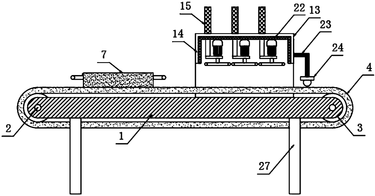
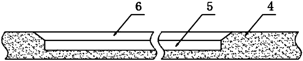
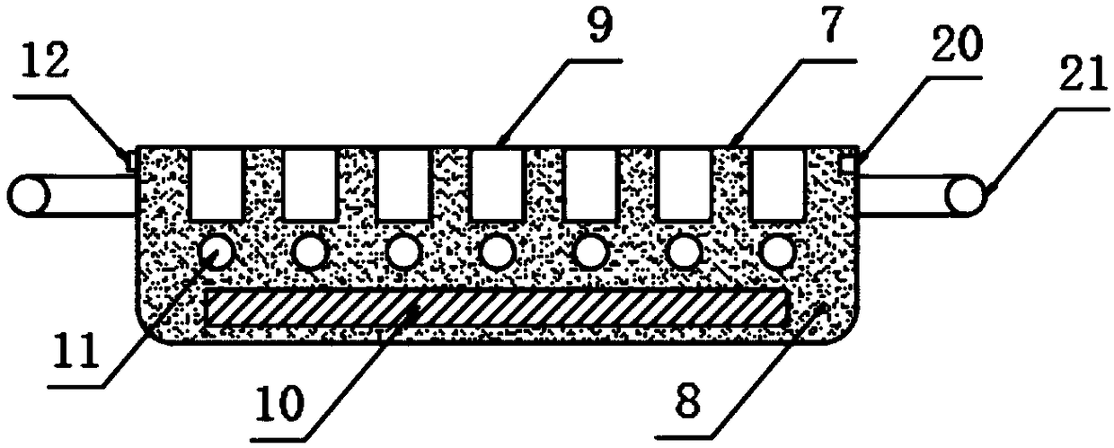
[0026] The present invention provides such as Figure 1-5 The high-efficiency grinding equipment shown includes a bed side plate 1, a drive shaft 2 is arranged between the bed side plates 1, and a rotating roller 3 is sleeved on the outside of the drive shaft 2, and the rotating roller 3. A conveyor belt 4 is sleeved on the outer side. The conveyor belt 4 is provided with a fixing groove 5 and a guide groove 6. The guide groove 6 is arranged on the top of the fixing groove 5. The inside of the fixing groove 5 is provided with a bearing mechanism 7. The carrying mechanism 7 includes a mold main body 8, the top of the mold main body 8 is provided with an accommodation groove 9, the inside of the mold main body 8 is provided with a battery 10 and a first electromagnet 11, and a side of the mold main body 8 is provided with a push switch 12. A grinding mechanism 13 is fixed on the top of the bed side plate 1 .

[0027] It can be seen from the above-mentioned embodiments that the ...

Embodiment 2

[0029] Further, in the above-mentioned embodiment 1, the fixing groove 5 is matched with the bearing mechanism 7, and the cross section of the guide groove 6 is set as an inverted equilateral trapezoid, so as to play a guiding role, so that the bearing mechanism 7 can be placed more easily In the fixed slot 5;

[0030] The first electromagnet 11 is arranged on the top of the battery 10, and the first electromagnet 11 is arranged on the bottom of the receiving tank 9;

[0031] The other side of the mold main body 8 is provided with a charging socket 20 for charging the battery 10, and both sides of the mold main body 8 are fixed with handles 21, so that the carrying mechanism 7 can be taken more conveniently;

[0032] The grinding mechanism 13 includes a cover body 14, the top of the cover body 14 is fixedly provided with a cylinder 15, the bottom end of the cylinder 15 is fixedly arranged on a mounting plate 16, and the top of the mounting plate 16 is provided with a variable ...


PUM


Abstract

The invention discloses efficient polishing equipment. The efficient polishing equipment comprises bed body lateral plates. A transmission shaft is arranged between the bed body lateral plates. A rotating roller is arranged outside the transmission shaft in a sleeving mode. A conveying belt is arranged outside the rotating roller in a sleeving mode. The conveying belt is provided with a fixing groove and a guide groove. The guide groove is formed in the top of the fixing groove. The fixing groove is internally provided with a load bearing mechanism. The load bearing mechanism comprises a moldbody. A storing groove is formed in the top of the mold body. The mold body is internally provided with a storage battery and a first electromagnet. A pressing switch is arranged on one side of the mold body. A polishing mechanism is fixedly arranged at the tops of the bed body lateral plates. Through the load bearing mechanism, a plurality of metal parts can be machined at the same time after loading and assembling, only one or two operators are required in actual operation, and therefore the number of required personnel is effectively decreased, the manufacturing cost is lowered, labor intensity in the whole polishing process is reduced meanwhile, and polishing quality is guaranteed.

Description

technical field [0001] The invention relates to the technical field of grinding, in particular to a high-efficiency grinding equipment. Background technique [0002] In the production process of a variety of smaller metal parts, it is necessary to grind the metal parts. The grinding methods used in the prior art are mostly manual grinding with electric grinders. Only a single piece can be processed manually at a time, so more grinding workers are needed, which increases the production cost. At the same time, continuous repeated grinding operations will also increase the labor intensity of the grinding workers and affect the grinding quality. [0003] Therefore, it is necessary to invent a kind of high-efficiency grinding equipment to solve the above problems. Contents of the invention [0004] The purpose of the present invention is to provide a high-efficiency grinding equipment. By using the carrying mechanism to load a plurality of metal parts and then process them sim...

Claims


Application Information

Patent Timeline
Patent Type & Authority Applications(China)
IPC IPC(8): B24B19/00B24B41/06B24B41/00B24B55/00
CPCB24B19/00B24B41/005B24B41/06B24B55/00
Inventor 陈保锋
Owner 佛山市同鑫智能装备科技有限公司
Why Eureka
Try Eureka