Printer rotor containing rack

A technology for placing racks and printers, applied in the field of placing racks, can solve problems such as personal injury, rotor damage, slipping, etc., to avoid damage and prevent collisions

Inactive Publication Date: 2018-11-23
重庆市江津区天天印务有限责任公司
View PDF1 Cites 1 Cited by
  • Summary
  • Abstract
  • Description
  • Claims
  • Application Information

AI Technical Summary

Problems solved by technology

However, the two ends of the rotor placed on the rack are exposed, which is easy to collide with the operator and c

Method used


Image

  • Printer rotor containing rack
  • Printer rotor containing rack
  • Printer rotor containing rack

Examples


Embodiment 1

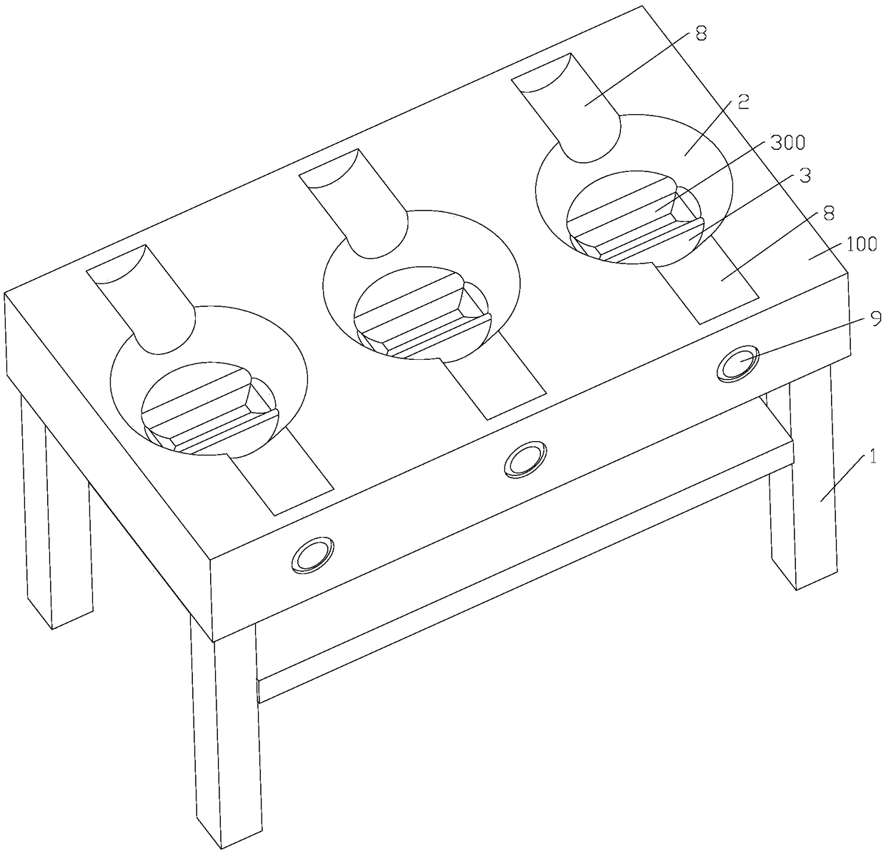
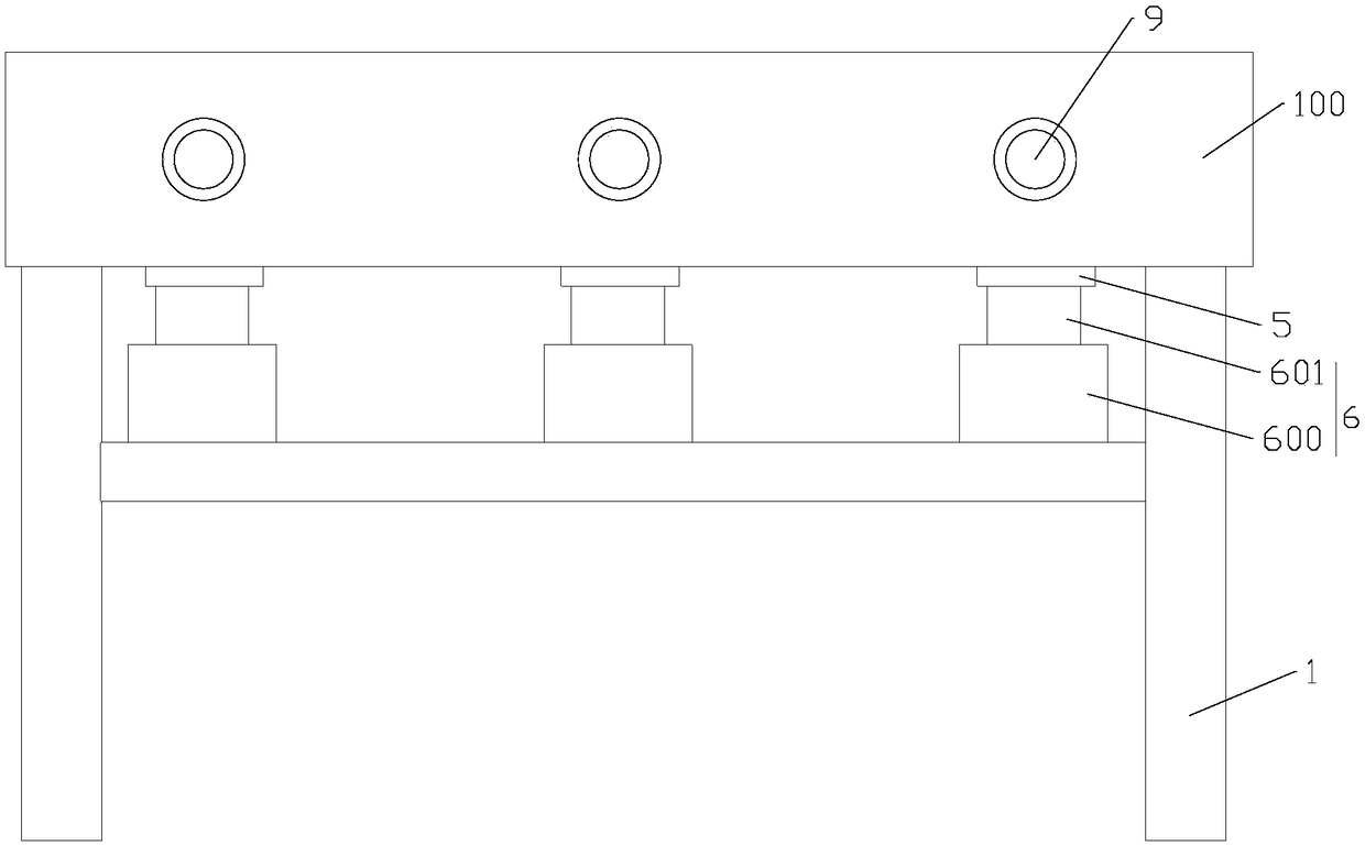
[0035] Such as Figure 1-Figure 4 , the printer rotor rack of the present invention, the printer rotor includes a rotor body and a shaft, including a rack body 1, a plurality of rotor body accommodation cavities 2, a plurality of support bodies 3 and a plurality of shaft retainers. At least one shelf panel 100 is arranged on the shelf body 1 , and the shelf panel 100 is square, as shown in the figure. In other embodiments, the shelf panel 100 can also have other shapes. The shelf panel 100 is provided with a plurality of rotor body accommodation cavities 2, the top of the rotor body accommodation cavity 2 is flush with the upper surface of the shelf panel 100, the bottom end of the rotor body accommodation cavity 2 is located in the placement shelf panel 100, and more Two rotor body accommodating cavities 2 are arranged vertically, and the cross section of the rotor body accommodating cavity 2 is circular, as shown in the figure. In other embodiments, the cross section of the ...

Embodiment 2

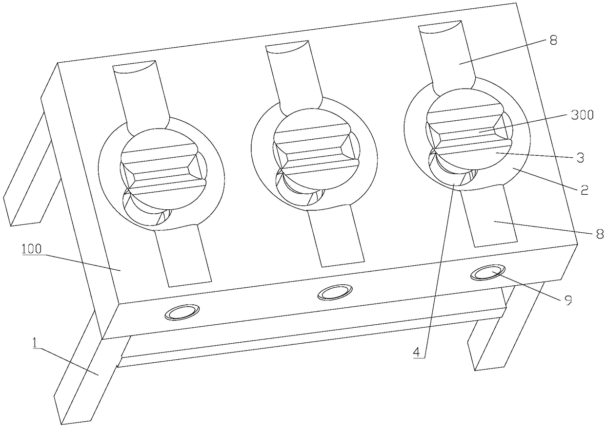
[0049] Such as Figure 4 , the printer rotor rack of the present invention, the printer rotor includes a rotor body and a shaft, including a rack body 1, a plurality of rotor body accommodation cavities 2, a plurality of support bodies 3 and a plurality of shaft retainers. At least one shelf panel 100 is arranged on the shelf body 1 , and the shelf panel 100 is square, as shown in the figure. In other embodiments, the shelf panel 100 can also have other shapes. The shelf panel 100 is provided with a plurality of rotor body accommodation cavities 2, the top of the rotor body accommodation cavity 2 is flush with the upper surface of the shelf panel 100, the bottom end of the rotor body accommodation cavity 2 is located in the placement shelf panel 100, and more Two rotor body accommodating cavities 2 are arranged vertically, and the cross section of the rotor body accommodating cavity 2 is circular, as shown in the figure. In other embodiments, the cross section of the rotor bod...


PUM


Abstract

The invention discloses a printing paper storage rack, and relates to a printer rotor containing rack. The printer rotor containing rack comprises a containing rack body. At least one containing rackpanel is arranged on the containing rack body. A printer rotor comprises a rotor body and a rotating shaft. The printer rotor containing rack is characterized by further comprising multiple rotor bodycontaining cavities, multiple supporting bodies and multiple rotating shaft protection parts; the multiple rotor body containing cavities are arranged on the containing rack panel; the multiple supporting bodies are arranged in at least part of the multiple rotor body containing cavities correspondingly; and the multiple rotating shaft protection parts are arranged on the two sides of at least part of the rotor body containing cavities correspondingly. According to the printer rotor containing rack, the supporting bodies can support the rotor bodies, the rotor bodies are located in the rotorbody containing cavities, the rotating shaft protection parts can protect the rotating shafts of the rotors, the rotating shafts of the rotors are not exposed out, damage is avoided, and colliding tooperation personnel can be avoided; and the rotor body is located in the rotor body containing cavities, so that the rotor cannot slide down.

Description

technical field [0001] The invention relates to a placement frame, in particular to a printer rotor placement frame. Background technique [0002] The patent document with the application number CN201520562708.6 discloses a magnetic rotor placement frame, which includes a placement frame body, at least one placement frame panel is arranged on the placement frame body, and two first magnetic rotors parallel to each other are arranged on each placement frame panel. The rotor placement plate and the second magnetic rotor placement plate, a set of matching magnetic rotor placement slots are arranged at intervals on the corresponding positions of the first magnetic rotor placement plate and the second magnetic rotor placement plate, and the magnetic rotors are placed in two corresponding magnetic rotor placement slots. on the slot. It is easy to access, occupies a small area, and can avoid broken magnetism caused by stacking. However, the two ends of the rotor placed on the rac...

Claims


Application Information

Patent Timeline
IPC IPC(8): B65D25/10B65D85/68B65D81/02
CPCB65D25/106B65D81/02B65D85/68
Inventor 邹仲山
Owner 重庆市江津区天天印务有限责任公司
Why Eureka
Try Eureka