Shield machine with multi-section spherical hinge structure
A technology of shield machine and spherical hinge, which is applied in mining equipment, earthwork drilling, tunnels, etc. It can solve the problems of small deflection range, external liquid infiltration into the shield machine, unfavorable construction line design, etc., and improve the reliability of sealing , prevent catastrophic consequences, and facilitate the effect of construction line design
- Summary
- Abstract
- Description
- Claims
- Application Information
AI Technical Summary
Problems solved by technology
Method used
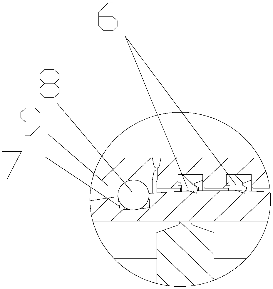
Image

Examples
Embodiment Construction
[0020] The present invention will now be described in further detail in conjunction with the accompanying drawings and preferred embodiments. These drawings are all simplified schematic diagrams, which only illustrate the basic structure of the present invention in a schematic manner, so they only show the configurations related to the present invention.
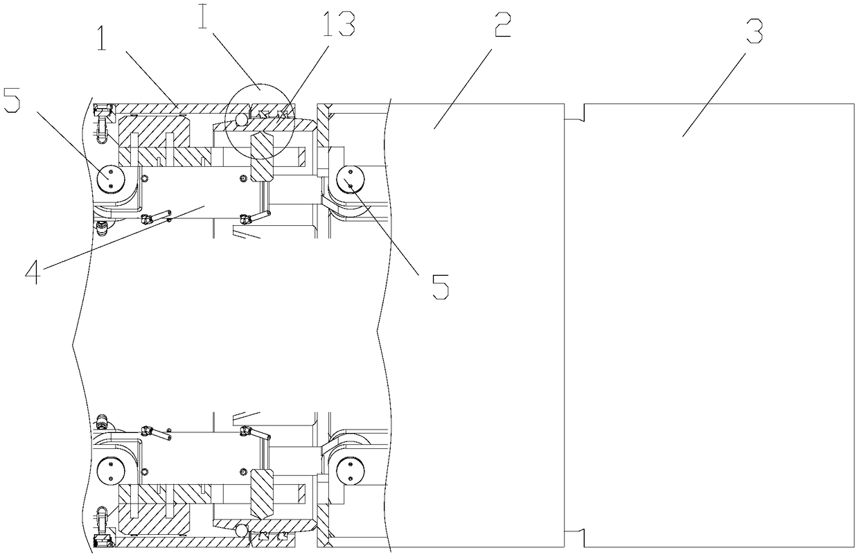
[0021] Such as Figure 1-2 A shield machine with a multi-section spherical hinge structure is shown, including a front shield 1, a middle shield 2, a tail shield 3 and a hinged oil cylinder 4, and there is a spherical ring steering structure between the front shield 1 and the middle shield 2 ; There is a spherical ring steering structure between the middle shield 2 and the tail shield 3; because the spherical ring steering structure between the front shield and the middle shield, the middle shield and the tail shield is the same, so figure 1 Only the spherical ring steering structure of the front shield and the middle shiel...
PUM
 Abstract
Description
Claims
Application Information