Switch reluctance machine magnetic field analysis calculation method capable of considering saturation

A switched reluctance motor and magnetic field analysis technology, applied in calculation, electrical digital data processing, design optimization/simulation, etc., can solve the problems of switched reluctance motors that are difficult to move, cannot consider the tangential magnetic flux density, and the slot width is large

Active Publication Date: 2018-11-23
TONGJI UNIV
View PDF6 Cites 8 Cited by
  • Summary
  • Abstract
  • Description
  • Claims
  • Application Information

AI Technical Summary

Problems solved by technology

The analytical method based on the solution of the Laplace equation and the Poisson equation can only obtain the linear magnetic flux density, but the problem of local saturation of the magnetic field caused by the double salient pole structure of the switched reluctance motor is serious, and this method is difficult to consider the nonlinearity of the magnetic field; The analytical method based on the winding function theory can only obtain the radial flux density, and cannot consider the tangential flux density. Compared with other motors, the slot width of the switched reluctance motor is larger, resulting in serious tooth side excitation, so that the flux density has a large tangential component, so the tangential flux density cannot be ignored
At present, due to the lack of an effective analytical calculation method for the magnetic field of switched reluctance motors, it is difficult for researchers to optimize the design of torque fluctuation and noise of switched reluctance motors.

Method used


Image

  • Switch reluctance machine magnetic field analysis calculation method capable of considering saturation
  • Switch reluctance machine magnetic field analysis calculation method capable of considering saturation
  • Switch reluctance machine magnetic field analysis calculation method capable of considering saturation

Examples


Embodiment

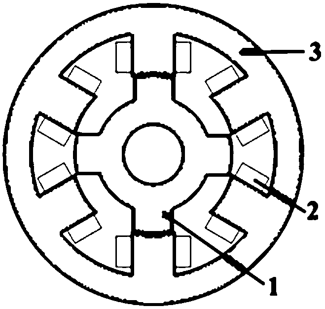
[0060] For a certain type of three-phase 6 / 4-pole switched reluctance motor with a rated speed of 4000r / m, the implementation test of the present invention is carried out.

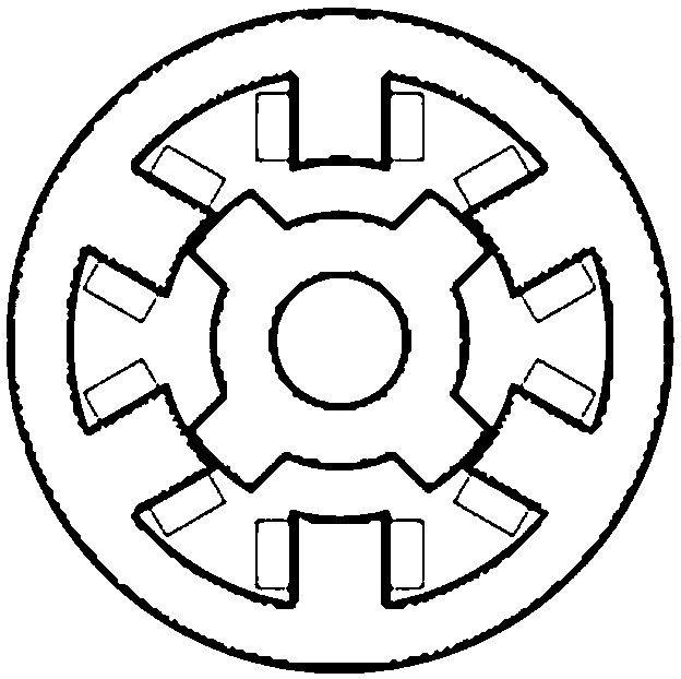
[0061] Fig. 1 is a schematic structural diagram of a traditional three-phase 6 / 4-pole switched reluctance motor in (a) aligned position and (b) non-aligned position. Among them, 1 is the rotor core, 2 is the winding, and 3 is the stator core. This method is used to analyze and calculate the air gap magnetic field distribution of the motor shown in Figure 1. The basic parameters of the motor are shown in Table 1.

[0062] Table 1 Basic parameters of three-phase 6 / 4-pole switched reluctance motor

[0063]

[0064]

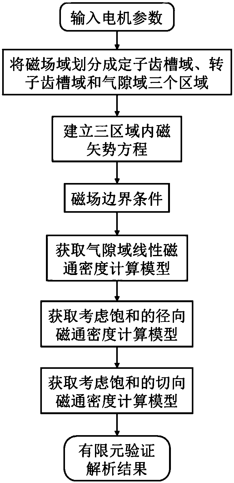
[0065] figure 2 Provide the flow of analytical calculation method of switched reluctance motor magnetic field considering saturation, including the following specific implementation steps:

[0066] Step 1, divide the research area into three areas: rotor cogging domain A, air gap domain...


PUM


Abstract

The invention relates to a switch reluctance machine magnetic field analysis calculation method capable of considering saturation. The method comprises the following steps that: 1) under a polar coordinate system, independently establishing the magnetic vector potential equations of a stator tooth socket domain, a rotor tooth socket domain and an air gap domain; 2) according to a magnetic field boundary condition and a relational expression between the magnetic vector potential and magnetic flux density, obtaining an air gap domain linear magnetic flux density parsing model; 3) under a Cartesian coordinate system, combining with the magnetic conductivity-magnetic flux density characteristic curve of a ferromagnetic material to obtain a radial magnetic flux density parsing model which considers the saturation; and 4) according to the saturation radial magnetic flux density, solving dynamic magnetic conductivity in a process, and further obtaining a tangential magnetic flux density analysis calculation model which considers the saturation. Compared with the prior art, the method is characterized in that the quick and accurate calculation of the switch reluctance machine air gap magnetic field is realized, and a theoretical basis is provided for designing a high-performance motor.

Description

technical field [0001] The invention relates to a method for calculating the magnetic field of a switched reluctance motor, in particular to an analytical calculation method for the magnetic field of a switched reluctance motor considering saturation. Background technique [0002] Switched reluctance motors have the advantages of strong robustness, simple structure, high temperature resistance, and low cost, so they are widely used in aerospace, electric vehicles, mining and other fields. However, compared with permanent magnet synchronous motors and induction motors, switched reluctance motors have larger torque fluctuations and noises, which hinder their further promotion in high-performance drive systems, so torque fluctuations and noises are the focus of designing switched reluctance motors think abut. However, the accurate calculation of the air gap magnetic field is the basis and premise of the optimal design of motor torque fluctuation and noise. The magnetic field ...

Claims


Application Information

Patent Timeline
Patent Type & Authority Applications(China)
IPC IPC(8): G06F17/50
CPCG06F30/23
Inventor 左曙光胡胜龙吴双龙邓文哲郑玉平刘明田
Owner TONGJI UNIV
Why Eureka
Try Eureka