
Method and equipment for debugging microwave cavity filter, and storage device

A microwave cavity and storage device technology, applied to waveguide devices, electrical components, circuits, etc., can solve problems such as difficult to accurately extract model parameters, difficult to extract coupling matrix, and filters that cannot reach the target, so as to improve debugging efficiency , shorten the debugging time, and the debugging process is simple

Active Publication Date: 2018-11-23
CHINA UNIV OF GEOSCIENCES (WUHAN)
View PDF9 Cites 8 Cited by
  • Summary
  • Abstract
  • Description
  • Claims
  • Application Information

AI Technical Summary

Problems solved by technology

However, after the microwave filter is designed according to strict specifications, due to the influence of processing accuracy and assembly error, the filter often fails to meet the design indicators after production.
In order to compensate for the impact of the production process, it is often necessary to perform post-debugging on the filter. At present, the computer-aided debugging methods of microwave filters based on established models at home and abroad mainly include time-domain debugging method, coupling matrix extraction The equivalent circuit method, data-driven method and fuzzy logic rule method; the time domain debugging method requires standard templates, and requires workers to assist in debugging; the equivalent circuit method of coupling matrix extraction needs to extract the coupling matrix, but in high When the order is high, the coupling matrix is ​​difficult to extract and the method cannot give the rotation of the screw; the data-driven method requires a lot of data and a lot of time for training, and often needs to retrain the model for different filters, which is less efficient Low; the fuzzy logic rule method cannot be used to debug the cross-coupling filter
In summary, with model-based methods, model parameters are difficult to extract accurately, with data-driven methods, the model needs to be retrained, and fuzzy logic-based techniques cannot give adjustments, and cannot be applied to cross-coupled filters

Method used


Image

  • Method and equipment for debugging microwave cavity filter, and storage device
  • Method and equipment for debugging microwave cavity filter, and storage device
  • Method and equipment for debugging microwave cavity filter, and storage device

Examples


Embodiment Construction

[0023] In order to have a clearer understanding of the technical features, purposes and effects of the present invention, the specific implementation manners of the present invention will now be described in detail with reference to the accompanying drawings.

[0024] Embodiments of the present invention provide a method, device and storage device for debugging a microwave cavity filter.

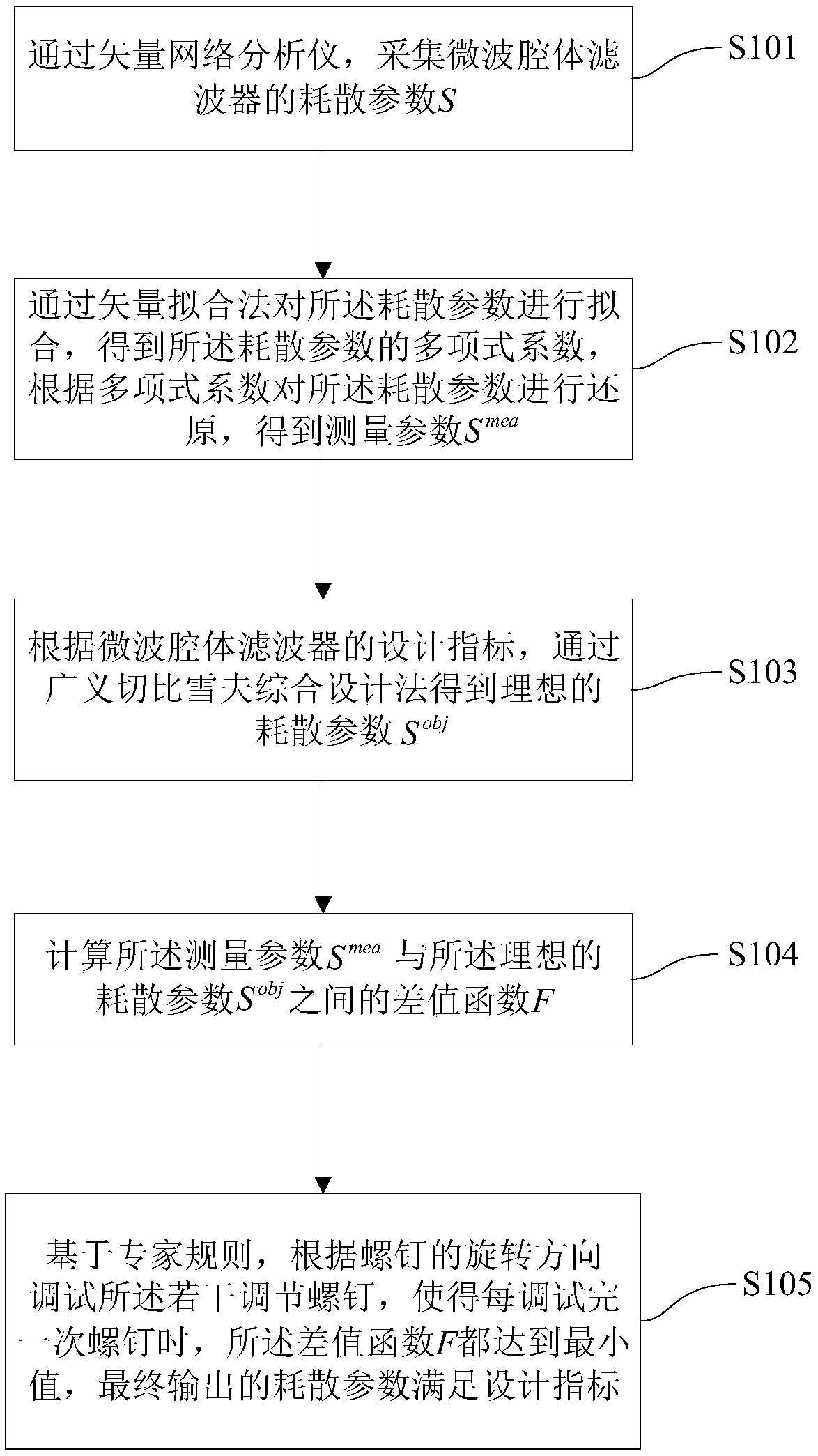
[0025] Please refer to figure 1 , figure 1 is a flowchart of a method for debugging a microwave cavity filter in an embodiment of the present invention, a method for debugging a microwave cavity filter, used for debugging a microwave cavity filter, and the microwave cavity filter The device has several adjusting screws, and the dissipation parameters of the microwave cavity filter are changed by adjusting the several adjusting screws; the method includes the following steps:

[0026] S101: Collect the dissipation parameter S of the microwave cavity filter through a vector network analyzer;...


PUM


Abstract

The invention provides a method and equipment for debugging a microwave cavity filter, and a storage device. According to the method, a polynomial coefficient of an acquired dissipation parameter S isobtained through a vector fitting method, and then the dissipation parameter S is restored through the polynomial coefficient to obtain smooth and noiseless Smea; Sobj is obtained through a generalized Chebyshev integrated design method, and a difference function F between the Smea and the Sobj is calculated; and according to the sequence of screws, each screw is debugged in sequence, and when the F is the minimum, the next screw is replaced in sequence, and the finally output dissipation parameter meets a design index. The equipment for debugging the microwave cavity filter and the storage device are used for implementing the method for debugging the microwave cavity filter. The method for debugging the microwave cavity filter provided by the invention has the following beneficial effects: the method can be applied to the debugging of a cross-coupled filter, a model does not need to be established, and influences of phase offset and the like do not need to be removed, thus the debugging process is simple and rapid, the debugging time is shortened, and the debugging efficiency is improved.

Description

technical field [0001] The present invention relates to the technical field of microwave filters, in particular to a method, device and storage device for debugging microwave cavity filters. Background technique [0002] Microwave filters are essential components in wireless communication systems. Microwave filters are widely used in wireless systems. With the rapid development of wireless communication systems, more stringent index requirements are put forward for the design of microwave devices. However, microwave filters designed according to strict specifications often fail to meet the design specifications after production due to the influence of machining accuracy and assembly errors. In order to compensate for the impact of the production process, it is often necessary to perform post-debugging on the filter. At present, the computer-aided debugging methods of microwave filters based on established models at home and abroad mainly include time-domain debugging metho...

Claims


Application Information

Patent Timeline
Patent Type & Authority Applications(China)
IPC IPC(8): H01P1/207H01P11/00
CPCH01P1/207H01P11/007
Inventor 曹卫华刘璨袁艳吴敏吴生彪庄晓龙毕乐宇过宇晟
Owner CHINA UNIV OF GEOSCIENCES (WUHAN)
Learn More