Electric coupler

A technology of electrical couplers and brushes, which is applied in the direction of coupling devices, circuits, electrical components, etc., can solve the problems of high driving accuracy requirements, high precision requirements, and damage to electrical couplers, so as to increase the scope of application and ensure Connection stability and the effect of improving the service life

Pending Publication Date: 2018-11-23
环球车享汽车租赁有限公司
View PDF0 Cites 1 Cited by
  • Summary
  • Abstract
  • Description
  • Claims
  • Application Information

AI Technical Summary

Problems solved by technology

However, in this way, the accuracy of the alignment of the two is very high during coupling, and the plug must be inserted to a specified depth to achieve contact with the terminals on both sides, which increases the difficulty of operation and is very inconvenient to use.
[0004] Furthermore, for a large electrical coupler, the coupling of two terminal parts is generally driven by the driving device to automatically drive one terminal part to move to align with the other terminal part, which requires high driving accuracy of the driving device. If there is no alignment, May cause damage to the electrical coupler during plug and socket connection

Method used


Image

  • Electric coupler
  • Electric coupler
  • Electric coupler

Examples


Embodiment Construction

[0060] Example embodiments will now be described more fully with reference to the accompanying drawings. Example embodiments may, however, be embodied in many forms and should not be construed as limited to the embodiments set forth herein; rather, these embodiments are provided so that this disclosure will be thorough and complete, and will fully convey the concept of example embodiments to those skilled in the art. The same reference numerals denote the same or similar structures in the drawings, and thus their repeated descriptions will be omitted.

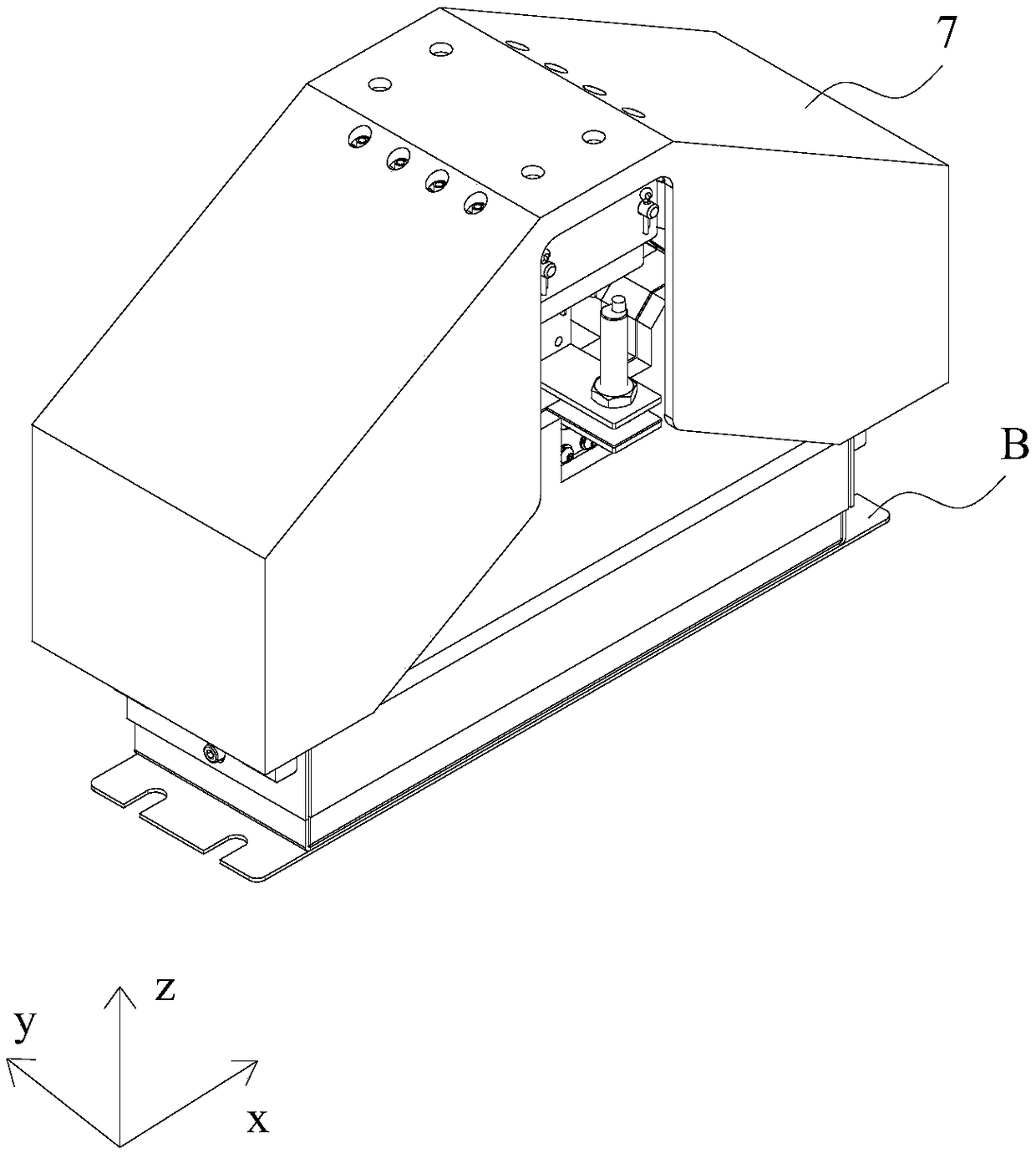
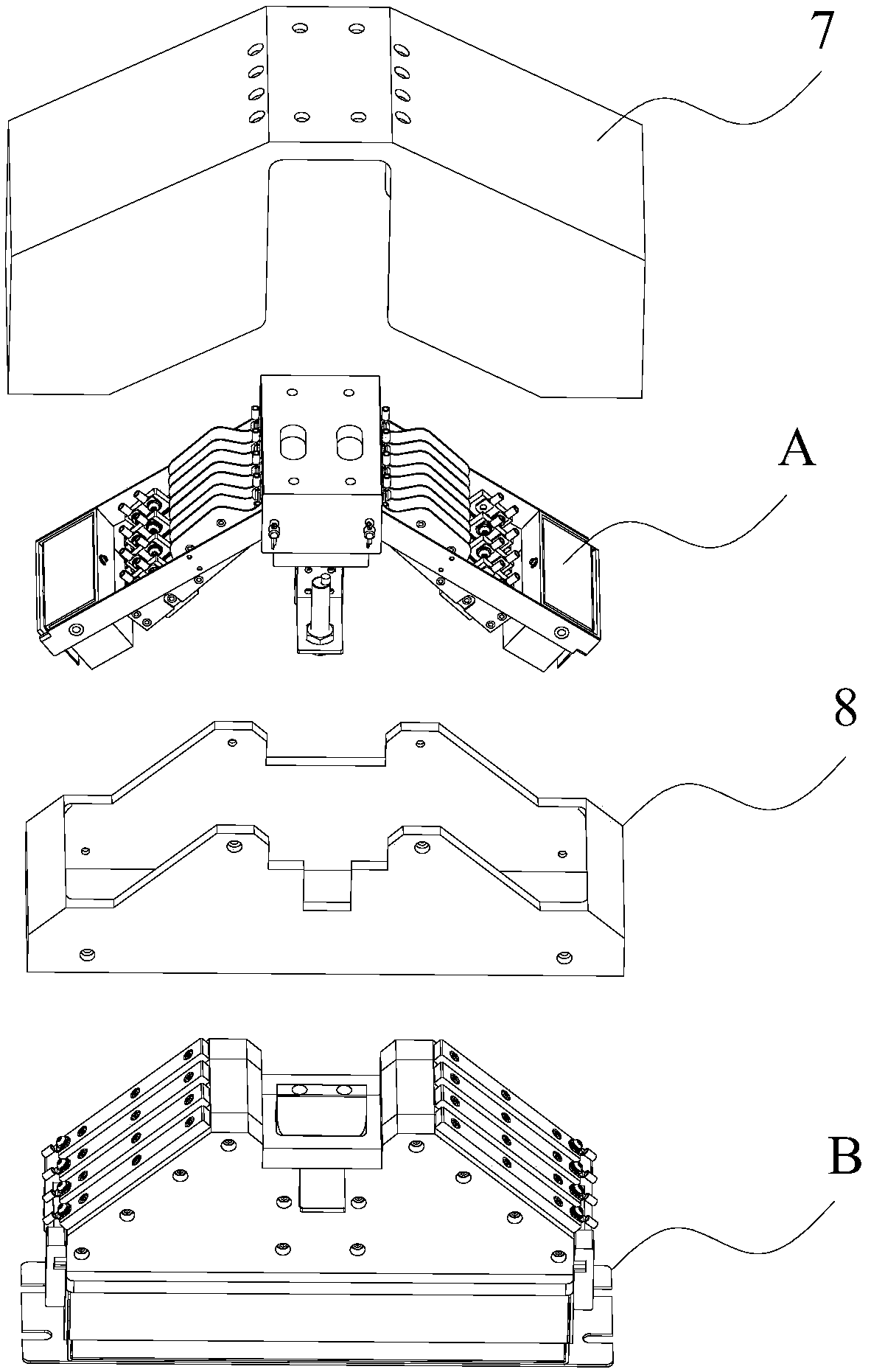
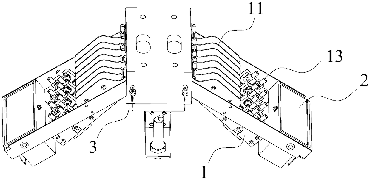
[0061] Such as Figure 1~5 As shown, the embodiment of the present invention provides an electrical coupler, including a first terminal part A and a second terminal part B, the outside of the first terminal part A has a first terminal part housing 7, and the outside of the second terminal part housing B There is a second terminal part housing 8 , wherein the first terminal part A includes a first terminal part support 3 , two...


PUM


Abstract

The invention provides an electrical coupler comprising a first terminal portion and a second terminal portion. The first terminal portion comprises: a first terminal portion bracket; two sets of brush swing arms, wherein one ends of the two sets of brush swing arms are respectively rotatably connected to the two ends of the first terminal portion bracket, and the other ends of each brush swing arm are respectively provided with at least one brush; and a first connecting terminal. The second terminal portion comprises: a second terminal portion bracket, wherein the middle part of one side surface of the second terminal portion bracket protrudes outwards to form two inclined planes which are inclined from the middle part to the two ends; two conductive plates, which are laid on the two inclined surfaces respectively; and a second connecting terminal. When the two terminal portions are coupled, the brushes of the two sets of brush swing arms are respectively in contact with the two conductive plates, and can slide to the two ends along the two conductive plates. According to the electric coupler, the electric brush, the brush swing arm and the lead plate are matched, so that a deviation error correction mechanism during coupling alignment is provided, and the requirement on the operation precision of a drive device of the coupler is reduced.

Description

technical field [0001] The invention relates to the technical field of electrical connection, in particular to an electrical coupler. Background technique [0002] The electrical coupler generally includes two terminal parts, and the two terminal parts are respectively provided with connecting terminals on one side. When the two terminal parts are coupled, the connecting terminals of the two terminal parts are in contact with each other, and one terminal part can be electrically connected to the power supply. , the electric energy can be connected from one terminal part to another terminal part, and then communicated to the device to be powered connected with the other terminal part, so as to implement power supply to the device. [0003] In the existing electrical coupler, the connecting terminals of the two terminal parts are often plug-in type. When coupling, the two connecting terminals need to be completely aligned, and the plug of one terminal part is inserted into the...

Claims


Application Information

Patent Timeline
Patent Type & Authority Applications(China)
IPC IPC(8): H01R13/631H01R13/02H01R13/502
CPCH01R13/6315H01R13/02H01R13/502
Inventor 曹光宇韦东波狄士春金勇喻杰潘明强兰天何爱萍骆欢
Owner 环球车享汽车租赁有限公司
Why Eureka
Try Eureka