

Optical fiber jumping fiber testing device
A testing device and optical fiber technology, applied in the direction of measuring devices, instruments, scientific instruments, etc., can solve the problems of low efficiency, cumbersome operation, and insufficient fixing, and achieve the effect of reducing costs, improving replacement efficiency, and saving the number of replacement connections
- Summary
- Abstract
- Description
- Claims
- Application Information
AI Technical Summary
Problems solved by technology
Method used
Image

Examples
Embodiment Construction
[0028] The technical solutions of the present invention will be further described below in conjunction with the accompanying drawings and through specific implementation methods.
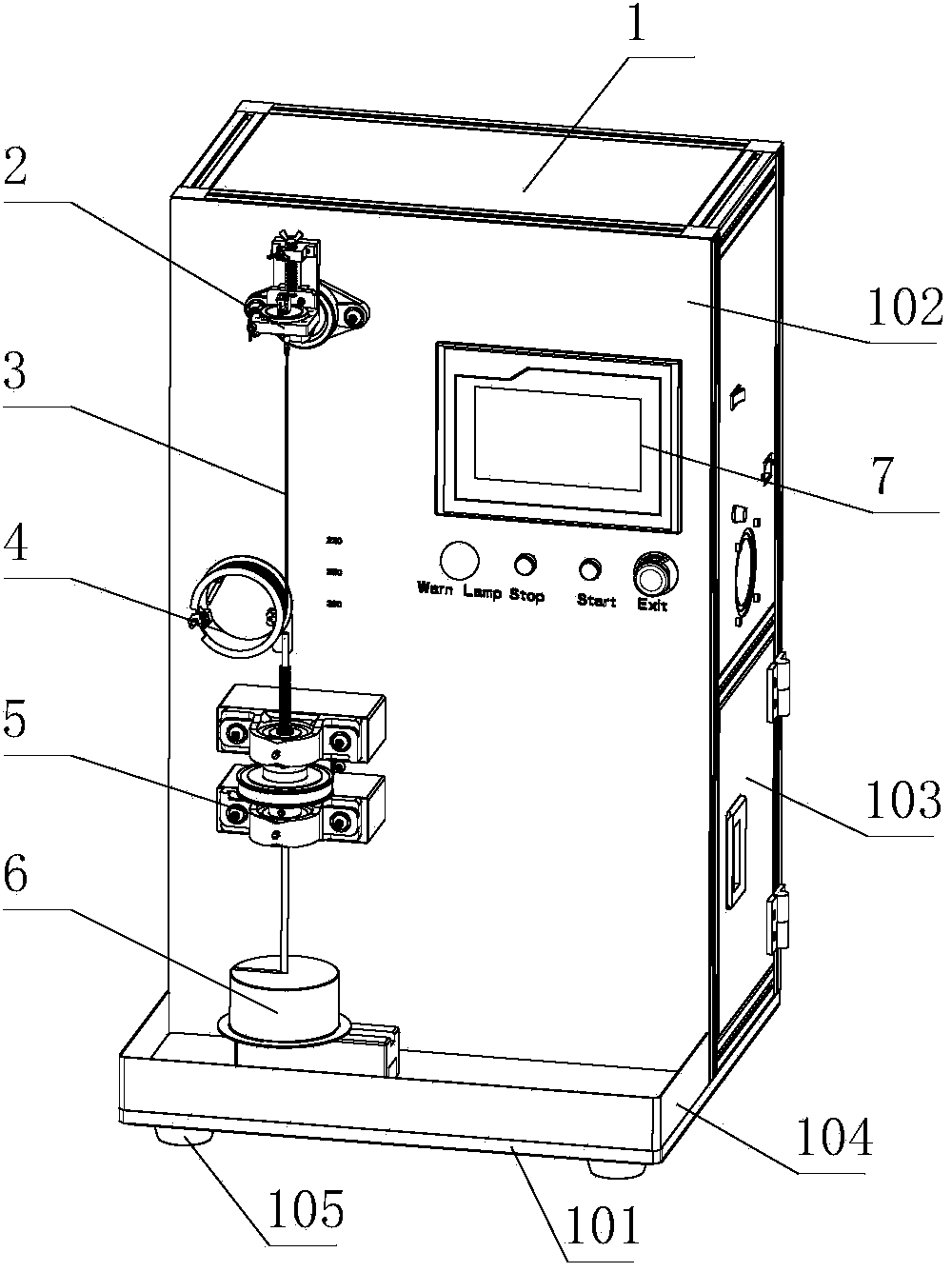
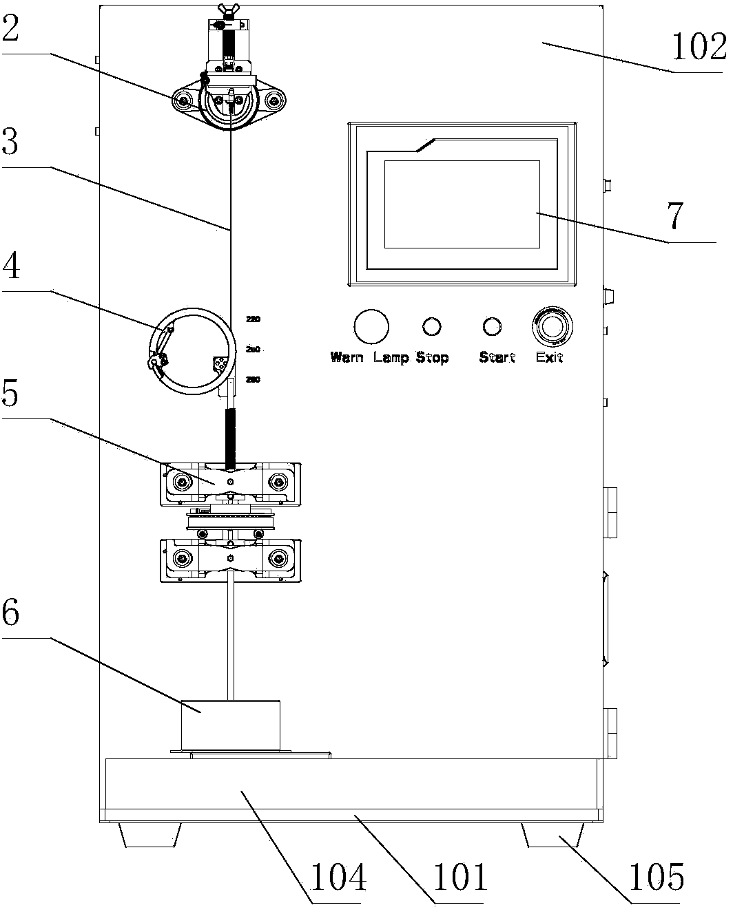
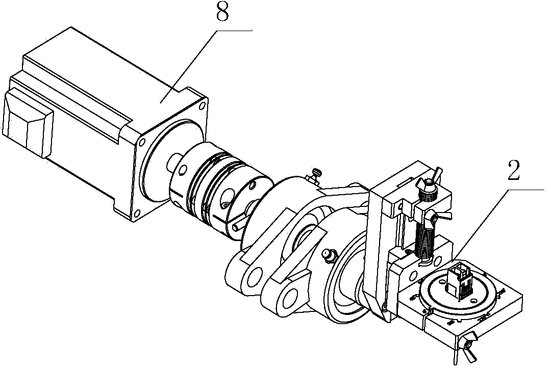
[0029] Such as Figures 1 to 9 As shown, a fiber jumper testing device includes a chassis 1, the front panel 102 of the chassis 1 is provided with a bending test clamping mechanism 2 that can rotate in the plane where the front panel 102 is located, and the bending test clamping mechanism 2 includes a limit body 203 , and an adapter mounting assembly for mounting the adapter 301 is detachably arranged on the limiting body 203 . In the optical fiber jumper testing device of the present invention, the adapter 301 of the optical cable connected with the jumper fiber is clamped and fixed by the adapter installation assembly of the bending test clamping mechanism 2, and the limiter 203 is used as the installation and fixing seat of the adapter installation assembly to Stable connection is realized, and ...
PUM
 Abstract
Description
Claims
Application Information