LCD display screen, electronic device, manufacturing method for LCD display screen

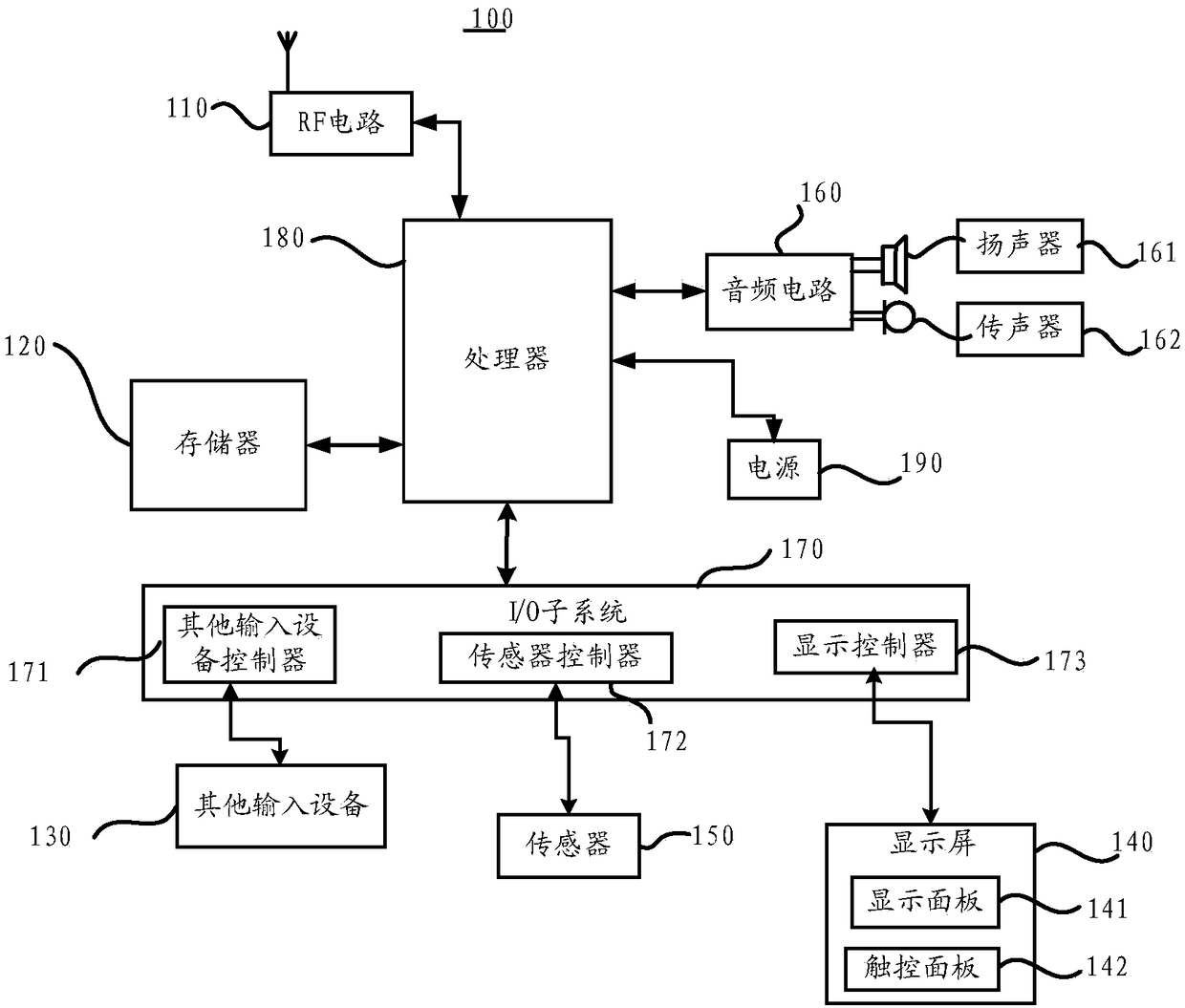
A production method and technology for electronic equipment, which are applied to branch equipment, equipment with sensors, computer monitor casings, etc. Improve visual experience, achieve full-screen effect, and increase screen-to-body ratio

Pending Publication Date: 2018-11-23
HUAWEI TECH CO LTD
View PDF7 Cites 123 Cited by
  • Summary
  • Abstract
  • Description
  • Claims
  • Application Information

AI Technical Summary

Problems solved by technology

However, the screen-to-body ratio of electronic devices has not broken through for a long time,

Method used


Image

  • LCD display screen, electronic device, manufacturing method for LCD display screen
  • LCD display screen, electronic device, manufacturing method for LCD display screen
  • LCD display screen, electronic device, manufacturing method for LCD display screen

Examples


Embodiment 1

[0162] In a possible embodiment, the first polarizer and the second polarizer are used, and the first polarizer and the second polarizer are partially cut off in a specific area. The light entering a specific area of ​​the first LCD glass substrate can be regarded as natural light; in addition, no non-high transmittance materials such as CF, metal current limiting and TFT devices are processed in this specific area, and the sealing silica gel is set, By making the specific area free of liquid crystals, most of the light can be transmitted through this area to achieve a partially transparent effect. Such as Figure 4 shown.

[0163] Specifically, the manufacturing method of the LCD display screen may include the following steps:

[0164] Step 1: According to the design requirements of the whole machine, determine the area of ​​the LCD display that needs to be transparent, and cut off the corresponding areas of the first and second polarizers in the LCD display. Cut off after...

Embodiment 2

[0174] The second embodiment of the present invention is to use the special-shaped first polarizer and the second polarizer, that is, the polarizer is partially cut off in a specific area, so that the light entering the specific area of ​​the LCD glass is still natural light; in addition, in the specific area Do not produce non-high transmittance materials, such as CF, metal circuits and TFT devices, etc.; and make the alignment film in this area invalid, and the liquid crystal presents a chaotic orientation, which is an isotropic material, allowing most of the light to pass through the area normally. area to achieve partial transparency; other transparent materials may not be processed, such as alignment film and ITO wiring, to further increase the transmittance. Such as Figure 9 shown.

[0175] Step 1: According to the design requirements of the whole machine, determine the area of ​​the LCD display that needs to be transparent, and cut off the corresponding areas of the f...

Embodiment 3

[0184] Embodiment 3 Embodiment 3 of the present invention is to design a local non-display area in the display area of ​​the LCD display screen. This area has no liquid crystal, metal wiring, TFT devices and other structures, and by cutting off this area, most of the light is normal. Through this area, the effect of local transparency is realized, such as Figure 12 shown.

[0185] Specifically, the manufacturing method of the LCD display screen may include:

[0186] Step 1: According to the design requirements of the whole machine, determine the partially transparent area of ​​the LCD display, cut off the corresponding areas of the first and second polarizers in the LCD display, and attach the polarizers to the first and second LCDs The front cutting of the glass substrate can also be cut off together with the first and LCD glass substrates after lamination. The transparent area can be entirely inside the display area or at the edge of the display area.

[0187] Step 2: Ac...


PUM


Abstract

An LCD display screen (140), an electronic device, and a manufacturing method for the LCD display screen (140). The LCD display screen (140) comprises several light-transmissive material layers and several non-light-transmissive material layers that are stacked; the LCD display screen (140) has a local light-transmissive area (31); the several non-light-transmissive material layers have no non-light-transmissive material in the local light-transmissive area (31) so as to form a light-transmissive channel in the local light-transmissive area (31) along a stack direction; some or all of opticaldevices are configured in the light-transmissive channel of the LCD display screen (140). By means of the local light-transmissive area (31) of the LCD display screen (140), the optical devices such as a camera (230), an ambient light sensor, and an optical fingerprint sensor, and other devices can be placed below the LCD display screen (140), and thus, the screen-to-body ratio is greatly enhanced, and a full screen effect is achieved.

Description

technical field [0001] The invention relates to the field of LCD display screens, in particular to an LCD display screen, electronic equipment and a manufacturing method of the LCD display screen. Background technique [0002] Currently, electronic devices with large-sized liquid crystal displays (LCDs) are more favored by consumers. However, the screen-to-body ratio of electronic devices has not yet broken through and failed to meet consumer expectations, resulting in an unsightly appearance of electronic devices. As the competition for electronic equipment becomes fiercer, the appearance becomes an important factor for consumers to purchase electronic equipment when the functions of the electronic equipment are almost the same. Therefore, increasing the screen-to-body ratio of electronic equipment is the main direction for electronic equipment manufacturers in the future. Contents of the invention [0003] Embodiments of the present invention provide an LCD display scr...

Claims


Application Information

Patent Timeline
IPC IPC(8): G02F1/1341G02F1/1333
CPCG02F1/1333G02F1/133528G02F1/1336G02F1/133514G02F1/1368H04M1/0266H04M1/02H04M1/0264H04M2250/12H04N2007/145H04N7/142G06F1/1626G06F1/1643G06F1/1658G06F1/1686G06F1/1688G06F1/169G02F1/1341G06F1/1637G06F1/1605G02F1/133512G02B2027/0138G02F1/1337G02F1/1339G02F1/136209G02F2202/28G02F1/133302G02F1/133388G02F1/133565
Inventor 尹帮实杨帆严斌薛康乐陈晓萌
Owner HUAWEI TECH CO LTD
Why Eureka
Try Eureka