
Dust removal equipment

A technology for dust removal equipment and casings, which is applied in the direction of devices where the axial direction of the swirl flow can be reversed, swirl flow devices, etc., which can solve the problems of inconvenient disassembly, time-consuming cleaning, and the inability to constantly detect the integrity of the casing of the cyclone dust removal equipment, etc. problem, to achieve the effect of simple structure, avoiding time and energy, and good sealing

Inactive Publication Date: 2018-11-27
江西柏立松科技环保设备制造有限公司
View PDF0 Cites 3 Cited by
  • Summary
  • Abstract
  • Description
  • Claims
  • Application Information

AI Technical Summary

Problems solved by technology

[0002] Cyclone dust removal equipment is a dust removal equipment that separates solid and liquid particles from airflow, or separates solid particles from liquid. However, with the development of science and technology, people's requirements for cyclone dust removal equipment are getting higher and higher. Can not meet people's needs, people need to be easy to disassemble and always detect the complete cyclone dust removal equipment; the existing cyclone dust removal equipment has certain disadvantages in use, first of all, when the existing cyclone dust removal equipment is installed, it is connected by welding And sealing, when it needs to be disassembled, it cannot be disassembled more conveniently. Secondly, the integrity of the inside of the cyclone dust collector cannot be checked from time to time. Finally, the interior of the cyclone dust collector cannot be cleaned automatically, and manual cleaning is required to waste time and energy. It has brought a certain impact on people's use process. For this reason, we propose a dust removal equipment

Method used


Image

  • Dust removal equipment
  • Dust removal equipment
  • Dust removal equipment

Examples


Embodiment Construction

[0018] In order to make the technical means, creative features, goals and effects achieved by the present invention easy to understand, the present invention will be further described below in conjunction with specific embodiments.

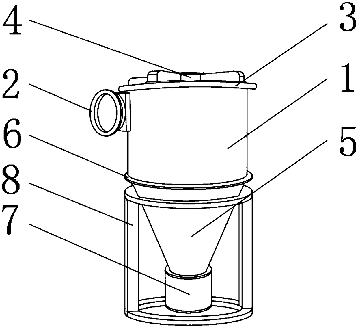
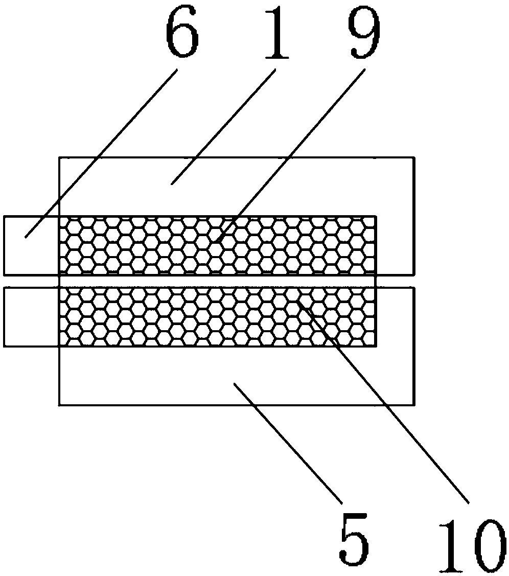
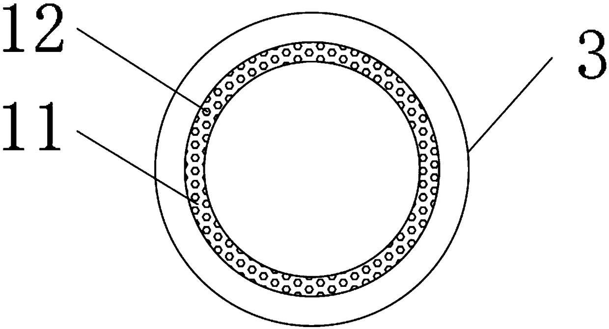
[0019] Such as Figure 1-4 As shown, a dust removal device includes a dust removal device housing 1, an air intake pipe 2 is fixedly installed on the outer surface of the dust removal device housing 1 near the top end, an upper end cover 3 is provided on the top outer surface of the dust removal device housing 1, and the upper end cover 3 An air outlet pipe 4 is fixedly installed at the center of the top outer surface, and a conical ash hopper 5 is provided under the dust removal equipment shell 1, and a connecting ring 6 is provided before the conical ash hopper 5 and the dust removal equipment shell 1, and the conical ash hopper 5 The outer surface of the bottom end of the dust storage tank 7 is fixedly installed, the outer surface of the conica...


PUM


Abstract

The invention discloses dust removal equipment. The dust removal equipment comprises a dust removal equipment shell, wherein an air inlet pipe is fixedly mounted at a position, close to the top end, of an outer surface of the dust removal equipment shell; an upper end cover is arranged on an outer surface of the top end of the dust removal equipment shell; and an air outlet pipe is fixedly mountedat the center of the outer surface of the top of the upper end cover. The dust removal equipment disclosed by the invention is provided with a No. 1 airbag, a copper wire net and a washing ring, so that the cyclone dust removal equipment can be more conveniently detached and replaced; meanwhile, the cyclone dust removal equipment can be sealed very well and a condition that dust flies out from agap to influence a dust removal effect is prevented; the integrality in the dust removal equipment shell can be more conveniently and rapidly detected, and certain potential safety hazards caused by the fact that the dust is caused and is not found in time are avoided; and the inner part of the cyclone dust removal equipment can be more conveniently washed, a condition that time and efforts are wasted, caused by manual washing, is avoided, and a better application prospect is brought.

Description

technical field [0001] The invention relates to the field of dust removal equipment, in particular to a dust removal equipment. Background technique [0002] Cyclone dust removal equipment is a dust removal equipment that separates solid and liquid particles from airflow, or separates solid particles from liquid. However, with the development of science and technology, people's requirements for cyclone dust removal equipment are getting higher and higher. Can not meet people's needs, people need to be easy to disassemble and always detect the complete cyclone dust removal equipment; the existing cyclone dust removal equipment has certain disadvantages in use, first of all, when the existing cyclone dust removal equipment is installed, it is connected by welding And sealing, when it needs to be disassembled, it cannot be disassembled more conveniently. Secondly, the integrity of the inside of the cyclone dust collector cannot be checked from time to time. Finally, the interio...

Claims


Application Information

Patent Timeline
Patent Type & Authority Applications(China)
IPC IPC(8): B04C5/00B04C5/23
CPCB04C5/00B04C5/23
Inventor 黄俊
Owner 江西柏立松科技环保设备制造有限公司
Learn More