Steel plate cut device

A cutting and equipment technology, applied in the field of steel plate cutting equipment, can solve problems such as time-consuming and inability to cut steel plates

Inactive Publication Date: 2018-11-27
ANHUI UNIVERSITY OF TECHNOLOGY AND SCIENCE
View PDF0 Cites 3 Cited by
  • Summary
  • Abstract
  • Description
  • Claims
  • Application Information

AI Technical Summary

Problems solved by technology

[0003] The object of the present invention is to provide a steel plate cutting equipment to solve the problems in the prior art that it takes a lot of time to cut the steel plate and it is impossible to select the corresponding steel plate according to the thickness of the steel plate by moving the steel plate. plate, the problem that thinner and thicker steel plates cannot be cut separately

Method used


Image

  • Steel plate cut device
  • Steel plate cut device
  • Steel plate cut device

Examples


Embodiment Construction

[0017] The following will clearly and completely describe the technical solutions in the embodiments of the present invention with reference to the accompanying drawings in the embodiments of the present invention. Obviously, the described embodiments are only some, not all, embodiments of the present invention. Based on the embodiments of the present invention, all other embodiments obtained by persons of ordinary skill in the art without making creative efforts belong to the protection scope of the present invention.

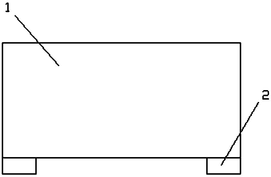
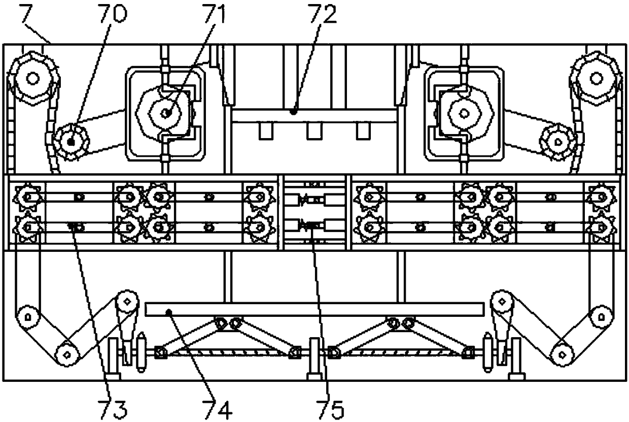
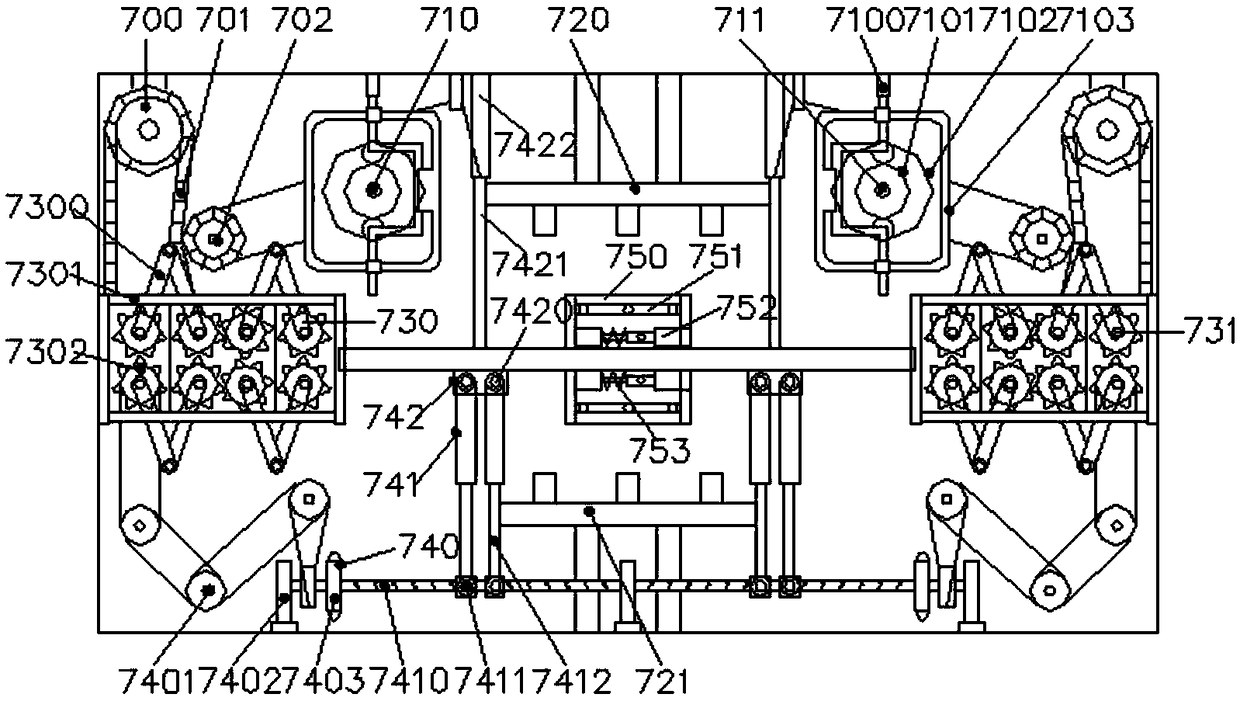
[0018] Such as Figure 1 to Figure 3 As shown, a steel plate cutting equipment includes a box body and a bracket, the bracket is arranged at the bottom of the box body, and is fixedly connected with the surface of the box body, the box body is provided with a cutting device, and the cutting equipment includes Chain transmission mechanism 70, roll-up structure 71, cutter 72, movable rack 73, liftable rack 74, movable buckle 75, the chain drive mechanism 70 is r...


PUM


Abstract

The invention discloses a steel plate cutting device, comprising a box body and a bracket, wherein the bracket is arranged at the bottom of the box body and is fixedly connected with the surface of the box body; the box body is provided with a cutting device; the cutting device comprises a chain transmission mechanism, a winding structure, a cutter, a movable rack, a liftable rack and a movable fastener; the cutting device comprises a chain transmission mechanism, a winding structure, a cutter, a movable rack, a liftable rack and a movable fastener. As that steel plate cut of the prior art takes a large amount of time, the steel plate placement plate can not be selecte according to the thickness of the steel plate through the movement of the steel plate placement plate, the thinner and thicker steel plates can not be cut separately, the utilization rate of the equipment can not be effectively improved, and the processing efficiency and the quality can not be effectively improved. The invention solves the problem that the steel plate cutting of the prior art takes a large amount of time, and the steel plate placement plate can not be selected according to the thickness of the steelplate.

Description

technical field [0001] The invention relates to the field of steel plate cutting equipment, in particular to a steel plate cutting equipment. Background technique [0002] The cutting of the steel plate in the prior art takes a lot of time, and it is impossible to select the corresponding steel plate according to the thickness of the steel plate by moving the steel plate, and it is impossible to cut thinner and thicker steel plates separately, and it is impossible to effectively improve the utilization rate of the equipment , the processing efficiency and quality cannot be effectively improved. Contents of the invention [0003] The purpose of the present invention is to provide a steel plate cutting equipment to solve the problems in the prior art that it takes a lot of time to cut the steel plate and it is impossible to select the corresponding steel plate according to the thickness of the steel plate by moving the steel plate. Plate, the problem that it is impossible t...

Claims


Application Information

Patent Timeline
Patent Type & Authority Applications(China)
IPC IPC(8): B23D79/00
CPCB23D79/00
Inventor 田丽陈松
Owner ANHUI UNIVERSITY OF TECHNOLOGY AND SCIENCE
Why Eureka
Try Eureka