Blanking execution mechanism of automatic feeding mechanism

A technology of automatic feeding and actuators, which is applied in packaging and other directions, to achieve the effect of reducing cost, reducing space occupancy, and compact structure

Pending Publication Date: 2018-11-27
陕西大中科技发展有限公司
View PDF0 Cites 2 Cited by
  • Summary
  • Abstract
  • Description
  • Claims
  • Application Information

AI Technical Summary

Problems solved by technology

[0004] The purpose of the present invention is to provide a blanking executive mechanism of the automatic feeding mechanism for the problems existing in the existing automatic feeding module. Blanking operations are performed on materials with specified shapes, and the materials in the blanking actuator will not be stacked, and there is no problem of jamming

Method used


Image

  • Blanking execution mechanism of automatic feeding mechanism
  • Blanking execution mechanism of automatic feeding mechanism
  • Blanking execution mechanism of automatic feeding mechanism

Examples


Embodiment 1

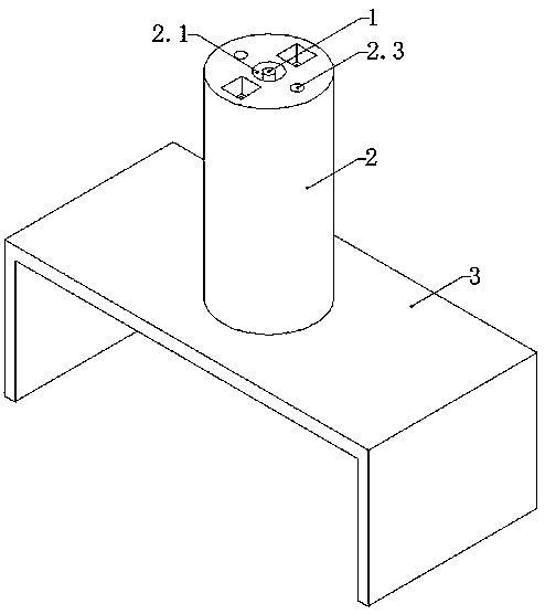
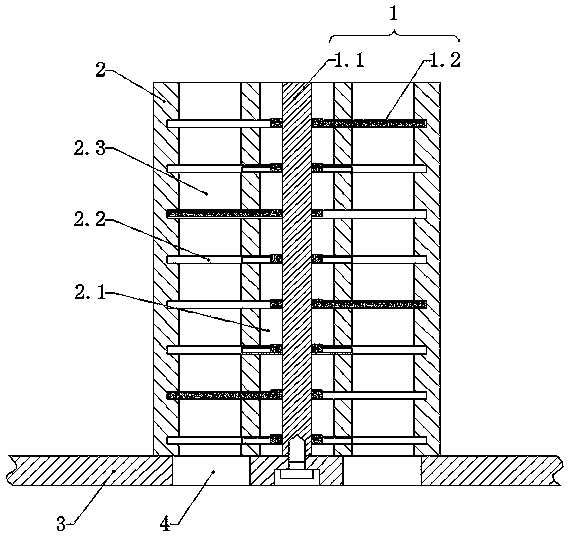
[0032] Such as Figure 2-3The blanking actuator of an automatic feeding mechanism shown includes a screw distributing shaft 1.1 assembly 1, and the screw distributing shaft 1.1 assembly 1 includes a distributing shaft 1.1 and a mutual cooperation set on the distributing shaft 1.1 at intervals. Two spiral receiving units, the spiral receiving unit includes four receiving fan pieces 1.2 arranged in a 360° radial spiral, and the four receiving fan pieces 1.2 are enclosed in a circle or ring shape; it also includes a material guide 2. The material guide 2 has a shaft channel 2.1 for accommodating the distributing shaft 1.1 and eight fan channels 2.2 for accommodating the rotation of two screw receiving units, as well as a corresponding receiving fan for the screw receiving unit 1.2 Matching four blanking channels 2.3, each blanking channel 2.3 respectively intersects with eight fan channels 2.2; wherein, the screw distribution shaft 1.1 component 1 is rotationally connected with t...

Embodiment 2

[0048] A blanking actuator of an automatic feeding mechanism, comprising a screw distributing shaft 1.1 assembly 1, the screw distributing shaft 1.1 assembly 1 includes a distributing shaft 1.1 and two interfitting mutually arranged distributing shafts 1.1 A spiral receiving unit, the spiral receiving unit includes four receiving fans 1.2 arranged in a 360° radial spiral, and the four receiving fans 1.2 are enclosed in a circle or ring shape; it also includes a material guide 2, the The material guide 2 has a shaft passage 2.1 for accommodating the distribution shaft 1.1 and eight fan passages 2.2 for accommodating the rotation of two spiral receiving units, and is used to cooperate with the corresponding receiving fans 1.2 of the spiral receiving unit There are four blanking channels 2.3, and each blanking channel 2.3 intersects with eight fan channels 2.2 respectively; wherein, the screw distribution shaft 1.1 assembly 1 is rotatably connected with the material guide 2.

[0...


PUM


Abstract

The invention discloses a blanking execution mechanism of an automatic feeding mechanism, and relates to the technical field of teaching equipment. The blanking execution mechanism comprises a material guiding piece and a rotatable spiral material dividing shaft assembly limited in the material guiding piece; the spiral material dividing shaft assembly comprises a material dividing shaft and at least two spiral collecting units arranged on the material dividing shaft at intervals, and at least two collecting fans on each spiral collecting unit are radially and spirally distributed on the material dividing shaft by 360 degrees; the material guiding piece is provided with an axial channel for containing the material dividing shaft, a plurality of fan channels for containing the spiral collecting units for rotation and a plurality of blanking channels for cooperating with the corresponding collecting fans of the spiral collecting units, and the blanking channels intersect with the fan channels. The blanking execution mechanism can blank materials one by one and stage by state without jamming, the material blanking operation of various kinds of materials different in shape and specification can be achieved simultaneously, the structure is compact, and the production and use cost is low.

Description

technical field [0001] The invention relates to the technical field of teaching equipment, in particular to a blanking actuator of an automatic loading mechanism. Background technique [0002] With the rapid development of artificial intelligence, industrial robots are gradually replacing humans in industrial production to do certain monotonous, frequent and repetitive long-term operations, or operations in dangerous and harsh environments, such as stamping, die casting, heat treatment, welding , painting, plastic product forming, mechanical processing and simple assembly and other processes, as well as in the atomic energy industry and other departments, to complete the handling or process operation of materials harmful to human body. However, the pace of development of industrial robot teaching lags behind the industry development of industrial robots. As an emerging field of education, the practical teaching of industrial robots is facing many challenges. Due to certain...

Claims


Application Information

Patent Timeline
Patent Type & Authority Applications(China)
IPC IPC(8): B65G33/14
CPCB65G33/14
Inventor 王天平王贵荣吴伟王爱兵周辉汪伟
Owner 陕西大中科技发展有限公司
Why Eureka
Try Eureka