
A lifting unit installation process for self-elevating drilling platform

A lifting unit, drilling platform technology, applied in artificial islands, water conservancy projects, infrastructure projects, etc., can solve problems such as low efficiency, damage to the pile fixing frame, and inability to achieve smooth installation in sequence

Active Publication Date: 2020-07-17
NANTONG BLUE ISLAND OFFSHORE CO LTD
View PDF7 Cites 0 Cited by
  • Summary
  • Abstract
  • Description
  • Claims
  • Application Information

AI Technical Summary

Problems solved by technology

[0003] During the installation process of the existing lifting unit, multiple lifting units are installed on the pile-fixing frame. The order of installing the lifting unit is complicated, and it is impossible to achieve a smooth installation. The traditional lifting unit is pulled to the pile-fixing frame by manpower, which is time-consuming and labor-intensive. It has high strength and low efficiency, and at the same time causes certain damage to the pile-fixing frame. The most important thing is that it is difficult to achieve the meshing degree between multiple lifting units and the rack. The connection between the lifting unit and the pile-fixing frame is extremely demanding. The traditional installation process Simply placing the lifting unit on the pile-fixing frame cannot guarantee the firmness and stability of the connection between the lifting unit and the pile-fixing frame
Therefore, it is necessary to propose a lifting unit installation process for jack-up drilling platforms that has simple and orderly steps, improves work efficiency, and ensures the firmness and stability of the connection between the lifting unit and the pile-fixing frame, which is bound to be welcomed by offshore construction personnel. After searching, no similar patents were found

Method used


Image

  • A lifting unit installation process for self-elevating drilling platform
  • A lifting unit installation process for self-elevating drilling platform
  • A lifting unit installation process for self-elevating drilling platform

Examples


Embodiment Construction

[0034] The following specific examples illustrate the implementation of the present invention. Those familiar with the technology can easily understand other advantages and effects of the present invention from the content disclosed in this specification.

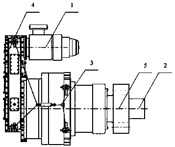
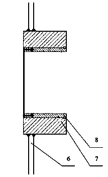
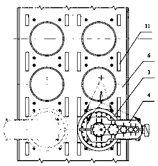
[0035] Such as figure 1 As shown, a lifting unit installation process for a jack-up drilling platform. The lifting unit includes a motor 1 and a gear box arranged front and rear. One end of the motor 1 is flush with one end of the gear box and is driven by a transmission member 4. The gear box includes a gear shaft 2 and a torque plate 3. The gear shaft 2 is arranged horizontally and the torque plate 3 is placed between the gear shaft 2 and the transmission member 4. The torque plate 3 is arranged perpendicular to the gear shaft 2, and the gear shaft 2 is covered with Climbing gear 5, including installation of sliding sleeve 8, cleaning of lifting unit, preliminary installation of lifting unit, cleaning of fixed pile frame 6, ...


PUM


Abstract

The invention discloses a mounting process of a lifting unit for a jack-up drilling platform, the lifting unit comprises a motor and a gearbox arranged in front and back, one end of the motor is arranged flush with one end of the gearbox, A gearbox includes a gear shaft, a torque plate disposed transversely and horizontally of the gear shaft and disposed between the gear shaft and the transmissionmember, the torque plate is arranged perpendicular to the gear shaft, The outer sleeve of the gear shaft is provided with a climbing gear, which is characterized in that the climbing gear comprises asliding shaft sleeve, a cleaning lifting unit, a preliminary installation lifting unit, a pile fixing frame cleaning, a lifting unit traction device positioning, a lifting unit traction device removing, a lifting unit torque plate mounting, a bearing seat cover plate mounting, a lifting unit adjustment pad mounting, and a lubrication pipeline arranging. The invention has the advantages of simpleand orderly steps, improving working efficiency, and ensuring the firmness and stability of the connection between the lifting unit and the pile fixing frame.

Description

Technical field [0001] The invention belongs to the field of offshore construction, and in particular relates to a lifting unit installation process for a jack-up drilling platform. Background technique [0002] With the increasing demand for petroleum energy in the global market and the continuous depletion of terrestrial petroleum energy, countries around the world have shifted their oil exploration sites from traditional land to oceans rich in oil and gas resources. Jack-up drilling rigs have always been the mainstream equipment for offshore oil exploitation in various countries due to their strong positioning capabilities, long life, low cost and high reliability. The lifting device in the drilling platform that can realize the lifting or lowering of the platform is one of the key components of the entire platform. It is the equipment that realizes the lifting and maintaining the lifting state of the jack-up drilling platform. [0003] During the installation process of the ex...

Claims


Application Information

Patent Timeline
Patent Type & Authority Patents(China)
IPC IPC(8): E02B17/04E02B17/08
CPCE02B17/04E02B17/08
Inventor 朱军苏小芳米智楠邹涛
Owner NANTONG BLUE ISLAND OFFSHORE CO LTD
Learn More