Portable solar self-generating tent

A technology of solar energy and self-generation, applied in tents/canopies, collectors, electric vehicles, etc., can solve problems such as inconvenient assembly and construction, lack of adjustment functions, and tents without self-power generation functions

Active Publication Date: 2018-11-27
界首市蒙特普休闲用品有限公司
View PDF6 Cites 2 Cited by
  • Summary
  • Abstract
  • Description
  • Claims
  • Application Information

AI Technical Summary

Problems solved by technology

Only by knowing the names and usage methods of each component and being familiar with the structure of the tent can we quickly and conveniently set up the tent. The existing tents do not have the function of self-power generation, do not have the

Method used


Image

  • Portable solar self-generating tent
  • Portable solar self-generating tent
  • Portable solar self-generating tent

Examples


Embodiment 1

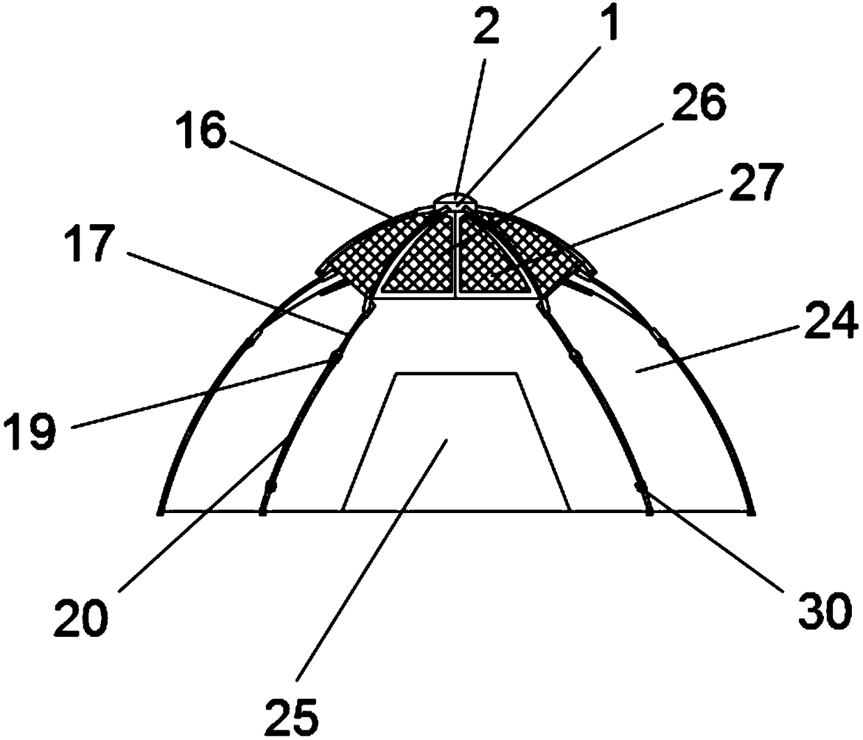
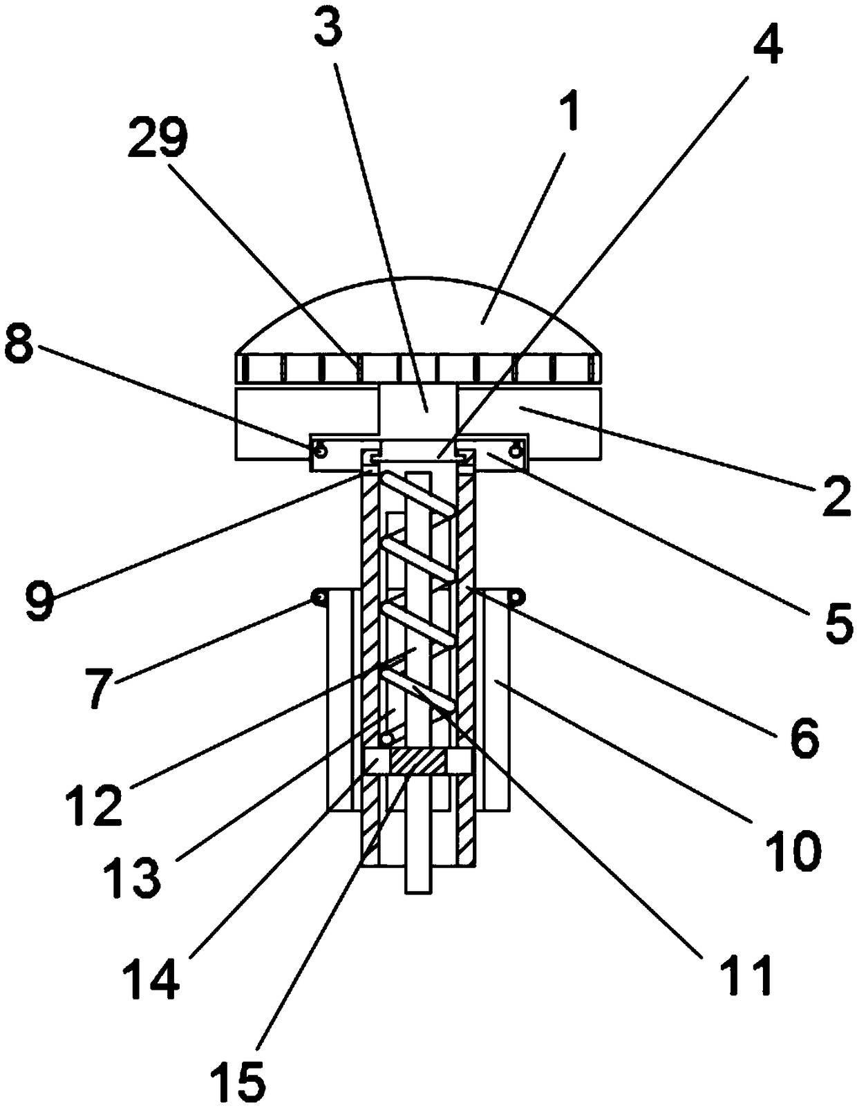
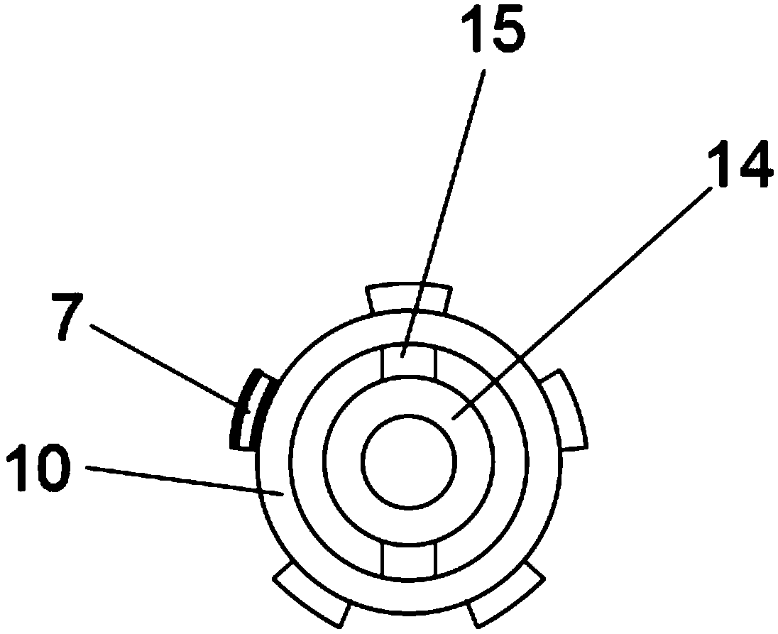
[0024] Embodiment 1: as Figure 1-6 As shown, a portable solar self-power generation tent includes a turning block 1, the outer wall of the turning block 1 is provided with anti-skid lines 29, the bottom of the turning block 1 is fixedly connected with a connecting shaft 3, and the outer side of the connecting shaft 3 The top ring 2 is movably socketed, the bottom of the coupling shaft 3 runs through the top ring 2 and is fixedly connected with a cover plate 5, the bottom of the cover plate 5 is fixedly connected with a key 4, and the bottom of the key 4 is movably engaged There is a sleeve 6, and guide grooves 13 are provided on both sides of the sleeve 6, and a bearing ring 14 is movably connected to the inner cavity of the sleeve 6, and a cable tube 12 is arranged in the bearing ring 14, and the cable The outer side of the tube 12 is wound with a spring 11, the spring 11 is located between the bearing ring 14 and the key 4, the outer side of the sleeve 6 is movably sleeved ...

Embodiment 2

[0025] Embodiment 2: as Figure 1-7 As shown, a portable solar self-power generation tent includes a turning block 1, the outer wall of the turning block 1 is provided with anti-skid lines 29, the bottom of the turning block 1 is fixedly connected with a connecting shaft 3, and the outer side of the connecting shaft 3 The top ring 2 is movably socketed, the bottom of the coupling shaft 3 runs through the top ring 2 and is fixedly connected with a cover plate 5, the bottom of the cover plate 5 is fixedly connected with a key 4, and the bottom of the key 4 is movably engaged There is a sleeve 6, and guide grooves 13 are provided on both sides of the sleeve 6, and a bearing ring 14 is movably connected to the inner cavity of the sleeve 6, and a cable tube 12 is arranged in the bearing ring 14, and the cable The outer side of the tube 12 is wound with a spring 11, the spring 11 is located between the bearing ring 14 and the key 4, the outer side of the sleeve 6 is movably sleeved ...


PUM


Abstract

The invention discloses a portable solar energy self-generating tent, Including transformers, the bottom of the rotating block is fixed with a fixing mechanism, comprises a top ring and a cover plate,the side wall of the top ring is rotatably connected with a plurality of first brackets, the outer wall of the sleeve is rotatably connected with a plurality of second brackets, the end of the firstbracket is movably articulated with the middle of the second bracket through a first hinge sleeve, the bottom of the second bracket is movably hinged with a third bracket through a second hinge sleeve, the lower outer wall of the sleeve is fixedly connected with a tent cloth, the bottom of the sleeve is movably connected with a top frame through the tent cloth, A battery is fixedly installed at the bottom of the top frame, A first solar panel and a second solar panel are movably connected between the adjacent first brackets, and the first solar panel and the second solar panel are movably articulated. The invention is convenient and firm to assemble and build, can be contracted and folded for storage and carrying, maintains the power supply demand in the tent by using the solar energy, andis easy to be popularized and applied.

Description

Technical field: [0001] The invention relates to the field of daily necessities, in particular to a portable solar self-generating tent. Background technique: [0002] A tent is a shed that is propped on the ground to shelter from wind, rain, sunlight and for temporary living. It is mostly made of canvas, and together with the supporting things, it can be removed and transferred at any time. The tent is carried in parts and assembled after arriving at the site, so various parts and tools are required. Only by knowing the names and usage methods of each component and being familiar with the structure of the tent can we quickly and conveniently set up the tent. The existing tents do not have the function of self-power generation, do not have the need to use solar energy to maintain the power supply in the tent, and are not convenient to assemble and build. Also does not have the adjustment function, the present invention provides a kind of tent that utilizes solar energy sel...

Claims


Application Information

Patent Timeline
IPC IPC(8): E04H15/02E04H15/44H02J7/35
CPCE04H15/02E04H15/44H02J7/35
Inventor 段永杰马汝霖段晓辉
Owner 界首市蒙特普休闲用品有限公司
Why Eureka
Try Eureka