Blade-type pneumatic motor

An air motor and vane-type technology, which is applied in the field of vane-type air motors, can solve the problems of position deviation between the rotation axis and the center of gravity of the motor, increased manufacturing costs, and poor overall stability, so as to increase output torque, reduce vibration, and improve stability. sexual effect

Inactive Publication Date: 2018-11-27
刘国强
View PDF5 Cites 3 Cited by
  • Summary
  • Abstract
  • Description
  • Claims
  • Application Information

AI Technical Summary

Problems solved by technology

If there is a high torque requirement, it is necessary to add a reducer at the output end to reduce the speed and increase the torque, but this will complicate the motor structure and increase the manufacturing cost
At the same time, due to the eccentric setting of the rotor, the current vane-type air motor causes a large deviation between the rotation axis and the center of gravity of the motor, so the working vibration is large and the overall stability is poor

Method used


Image

  • Blade-type pneumatic motor
  • Blade-type pneumatic motor
  • Blade-type pneumatic motor

Examples


Embodiment approach

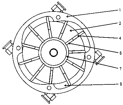
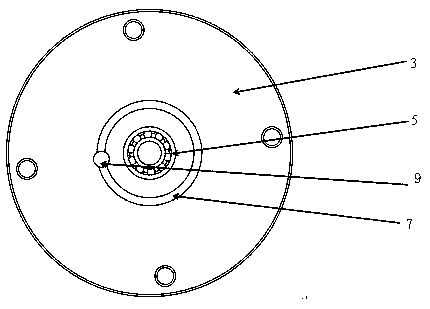
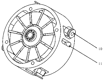
[0031] The optimal implementation mode: if Figure 1-3 A vane-type air motor is shown, including a housing 1, an end cover 3 and a rotor 2, the housing 1 and the end cover 3 are coupled and connected to form a rotor installation cavity between the two, the rotor is installed in the rotor installation cavity and One end in the axial direction of the rotor is the rotation output end, and the circumferential edge of the rotor 2 is provided with blade grooves 6 along the diameter direction, and the blade grooves 6 are distributed in the circumferential direction of the rotor 2, and blades 4 are slidably arranged in the blade grooves 6; its improved The point is that the rotor 2 and the rotor installation cavity are coaxially arranged, and the circumferential side wall of the rotor installation cavity is concaved outward to form a working chamber 8 for supplying airflow to push the blades to do work. The outer wall of the working chamber 8 is smooth Curved shape, the length of the ...


PUM


Abstract

The invention discloses a blade-type pneumatic motor, comprising a housing, an end cover and a rotor. The housing and the end cover are connected in butt-covering manner; a rotor mounting cavity is formed between the housing and the end cover; the rotor is mounted in the rotor mounting cavity; one axial end of the rotor is a rotation output end; the peripheral edge of the rotor is provided with blade grooves in the diameter direction; the blade grooves are distributed in the periphery of the rotor; blades are arranged slidably in the blade grooves. The blade-type pneumatic motor is characterized in that the rotor and the rotor mounting cavity are coaxial, the peripheral sidewall of the rotor mounting cavity is provided with a working chamber concaved outward and used for a flow to pushingthe blades to work; the outer wall of the working chamber is in smooth curve shape; the length of the blades is greater than a maximum distance from openings of the blade grooves to the outer wall ofthe working chamber; one end of the working chamber is provided with intake holes; the wall of the working chamber, in front of the intake holes in the rotation direction of the rotor, is provided with exhaust holes. The blade-type pneumatic motor has the advantages of small vibrations, better overall stability and higher output torque.

Description

technical field [0001] The invention relates to an air motor, in particular to a vane type air motor. Background technique [0002] Pneumatic motors, also known as wind motors, refer to devices that convert the pressure energy of compressed air into rotational mechanical energy. Generally used as a source of rotational power for more complex devices or machines. According to the structure, air motors are classified into: vane air motors, piston air motors, compact vane air motors, and compact piston air motors. Among them, vane air motors are smaller in size, lighter in weight and lower in cost than piston motors of similar power. Their simple design and structure enable them to operate at any installation angle in most cases. Therefore, the vane type air motor is the most commonly used form of air motor. [0003] The structure of the traditional vane air motor includes a housing, an end cover and a rotor. The housing and the end cover are coupled together to form a rotor...

Claims


Application Information

Patent Timeline
Patent Type & Authority Applications(China)
IPC IPC(8): F01C1/344F01C21/08F01C21/10F01C21/18
CPCF01C1/3446F01C21/08F01C21/104F01C21/18
Inventor 刘国强
Owner 刘国强
Why Eureka
Try Eureka