
Braking mechanism, brake friction plate wear limit alarm device and mounting method thereof

A wear limit and alarm device technology, applied in the direction of brake types, mechanical equipment, etc., can solve the problems that it is difficult to modify the brake system and brake shoes, there is no direct indicator, and the system is complicated, so as to achieve convenient and reliable use, reduce costs, and detect The effect of simple lines

Pending Publication Date: 2018-11-27
KNORR BREMSE BRAKE EQUIP SUZHOU CO LTD
View PDF8 Cites 0 Cited by
  • Summary
  • Abstract
  • Description
  • Claims
  • Application Information

AI Technical Summary

Problems solved by technology

In the system, the brake shoes need to be modified accordingly so that the insulation can be embedded in the brake shoes; and there are external power supplies and relays, the system is complicated, and it is difficult to modify the existing brake system and brake shoes
[0004] The synthetic brake shoe with alarm function introduced in the patent CN207080537U arranges coils in the insulating synthetic brake shoe body, and when the coil is rubbed against, the trigger signal is sent to the train system. Wiring grooves are opened inside the tile, and an external power supply is required at the same time, and there is no direct indicator
Based on these characteristics, there will be many restrictions in the application of this kind of alarm

Method used


Image

  • Braking mechanism, brake friction plate wear limit alarm device and mounting method thereof

Examples


Embodiment Construction

[0030] In order to enable those skilled in the art to better understand the solutions of the present invention, the following will clearly and completely describe the technical solutions in the embodiments of the present invention in conjunction with the drawings in the embodiments of the present invention. Obviously, the described embodiments are only It is an embodiment of a part of the present invention, but not all embodiments. Based on the embodiments of the present invention, all other embodiments obtained by persons of ordinary skill in the art without making creative efforts shall fall within the protection scope of the present invention.

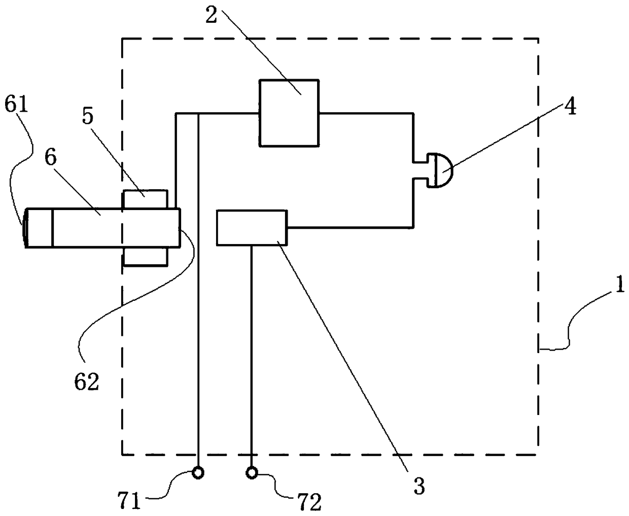
[0031] In one embodiment of the present invention, a brake pad wear limit alarm device is provided, see figure 1 , the alarm device includes a housing 1, a slide bar 6 and a power supply 2, a contact 3, an alarm 4 and a damping ring 5 arranged in the housing 1, and the housing 1 is directly or indirectly fixed on the brake On the f...


PUM


Abstract

The invention discloses a braking mechanism, a brake friction plate wear limit alarm device and a mounting method thereof. The alarm device comprises a shell, a slide bar and a power supply, a contactor, an alarm and a damping ring which are arranged in the shell, the shell is directly or indirectly fixed on a brake friction plate, and one end of the slide bar penetrates the outer wall of the shell to be matched with the damping ring; the power supply, the contactor, the alarm and the slide bar are in the same series circuit, and a wheel acts on the first end face of the slide bar when the brake friction plate is close to one side of the wheel to be flush with the first end face, extending out of one end of the shell, on the slide bar and in the process of braking the wheel with the brakefriction plate; with wearing of the brake friction plate, the wheel pushed the slide bar to move to the internal direction of the shell till the brake friction plate achieves wear limit, the second end face of the other end of the slide bar is contacted with the contactor, and the power supply is connected with the loop of the alarm. The alarm device is simple in structure, convenient in mounting,unaffected to an original brake system and highly accurate in wear monitoring.

Description

technical field [0001] The invention relates to the field of brake device detection, in particular to a brake friction plate wear limit alarm device, an installation method thereof, and a brake mechanism. Background technique [0002] In existing rail transit braking systems, tread braking is a widely used friction braking method. Tread braking converts kinetic energy into frictional heat energy through the friction between the brake shoe and the wheel, so there will be loss in the friction pair. If the brake shoe is worn to the limit, it will cause damage to the wheel or the braking system, and seriously cause Driving accidents affect production and transportation safety. Therefore, it is very important to detect whether the brake shoe is worn to the limit. At present, in the rail transit industry, there are not many ways to use the brake shoe wear limit alarm. [0003] The disclosed alarm as described in patent CN204704298U adopts an external power supply, and the sound...

Claims


Application Information

Patent Timeline
Patent Type & Authority Applications(China)
IPC IPC(8): F16D66/02
CPCF16D66/022
Inventor 陆爰年立胜张尚敬幸继松笪颖帆陆涛
Owner KNORR BREMSE BRAKE EQUIP SUZHOU CO LTD
Learn More