a circuit breaker

A circuit breaker, channel steel technology, applied in high-voltage air circuit breakers, circuits, high-voltage/high-current switches, etc., can solve the problems of fatigue fracture or dislocation of soft conductors, cumbersome assembly, and troublesome assembly, so as to save the isolation switch and Related devices, reduced assembly size, and the effect of easy assembly

Active Publication Date: 2022-04-05
SUCTRN TECH
View PDF13 Cites 0 Cited by
  • Summary
  • Abstract
  • Description
  • Claims
  • Application Information

AI Technical Summary

Problems solved by technology

[0004] However, the existing solid-sealed pole also has the following disadvantages: a soft connection is used between the electric contact and the moving end of the vacuum interrupter, that is, a soft conductor (such as a soft conductor) is used between the electric contact and the moving end of the vacuum interrupter. Copper) connection, the soft conductor can move together with the moving end of the vacuum interrupter, but the soft conductor has high processing cost, troublesome assembly, and requires high precision; moreover, with the increase in the number of uses, the soft conductor is prone to fatigue fracture or Abnormalities such as dislocation lead to failure of the embedded pole
[0005] Furthermore, in the prior art, the circuit breaker and the isolating switch are two independent components, and both need to be assembled independently in the switch cabinet, resulting in the problems of large volume and cumbersome assembly

Method used


Image

  • a circuit breaker
  • a circuit breaker
  • a circuit breaker

Examples


Embodiment Construction

[0037] To further illustrate the various embodiments, the present invention is provided with accompanying drawings. These drawings are a part of the disclosure of the present invention, which are mainly used to illustrate the embodiments, and can be combined with related descriptions in the specification to explain the operating principles of the embodiments. With reference to these contents, those skilled in the art should understand other possible implementations and advantages of the present invention. Components in the figures are not drawn to scale, and similar component symbols are generally used to denote similar components.

[0038] The present invention will be further described in conjunction with the accompanying drawings and specific embodiments.

[0039] In this embodiment, a circuit breaker of a two-phase power supply is taken as an example for illustration, but it is not limited thereto.

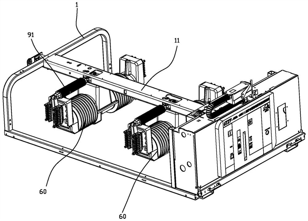
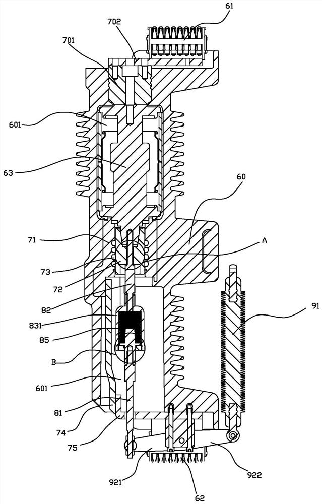
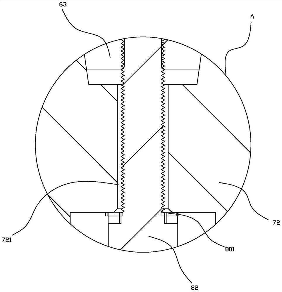
[0040] refer to Figure 1 to Figure 10 As shown, a circuit breaker pro...


PUM


Abstract

The invention provides a circuit breaker. The movable end of the vacuum interrupter of the pole is fixedly electrically connected to a movable conductive rod, and a lower outlet seat is provided in the accommodating cavity, and the movable conductive rod forms a sliding electrical connection with the lower outlet seat. When the movable end of the vacuum interrupter moves, it drives the movable conductive rod to move at the same time, and the movable conductive rod forms a sliding electrical connection with the lower outlet seat to replace the direct connection between the movable end of the vacuum interrupter and the soft conductor in the prior art. The lead-out circuit can be realized by directly connecting the hard copper bar with the lower outlet seat rigidly, with stable structure, easy assembly and low cost. The pole is set on the channel steel, and the channel steel is driven to rotate by the channel steel rotation drive mechanism. The rotation of the channel steel drives the pole to turn over, so that the pole is between the working state of connecting the external power supply end and the power consumption end and the detached storage state switch to realize the function of the isolating switch, save the isolating switch and related components, reduce the assembly volume, and simplify the assembly.

Description

technical field [0001] The invention relates to the field of circuit switches, in particular to a circuit breaker. Background technique [0002] Vacuum circuit breaker is named for its arc extinguishing medium and the insulating medium of the contact gap after arc extinguishing are both high vacuum; it has the advantages of small size, light weight, suitable for frequent operation, and no maintenance for arc extinguishing. The application is more popular. [0003] The main core component of the circuit breaker is the vacuum interrupter. In the past, the insulating shell of the general vacuum interrupter was exposed to the air, and there was a problem of being polluted by dust and moisture from the outside. In order to reduce this effect, the outer shell of the vacuum interrupter is required to have sufficient length, which not only affects the miniaturization of the vacuum interrupter, but also affects the performance and reliability of the vacuum interrupter. With the adv...

Claims


Application Information

Patent Timeline
Patent Type & Authority Patents(China)
IPC IPC(8): H01H33/664H01H33/666
CPCH01H33/664H01H33/6661
Inventor 彭开垦薛宝根林淡张群黄秋敏林画特程诺张振宇
Owner SUCTRN TECH
Why Eureka
Try Eureka