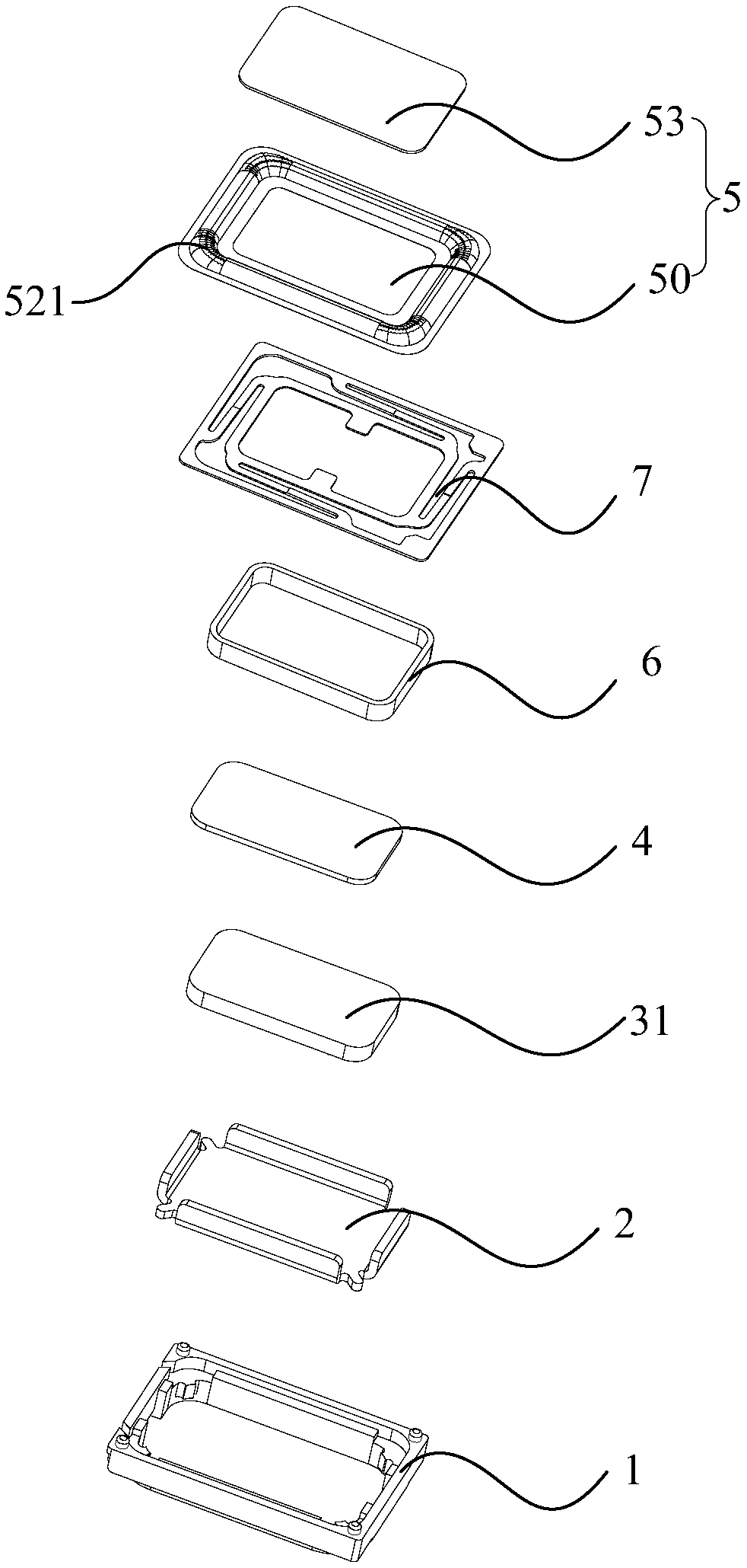
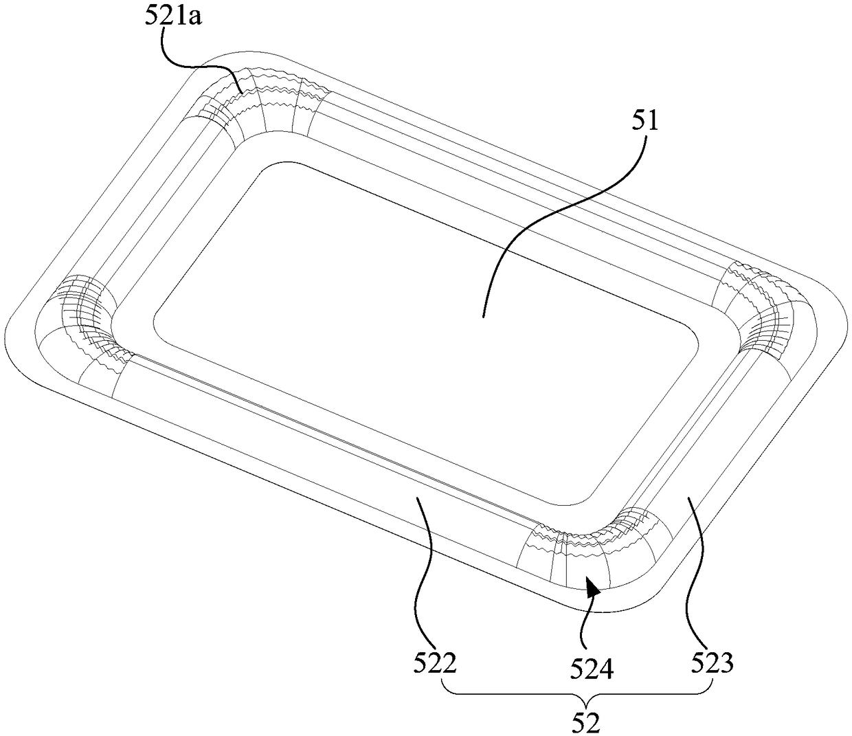
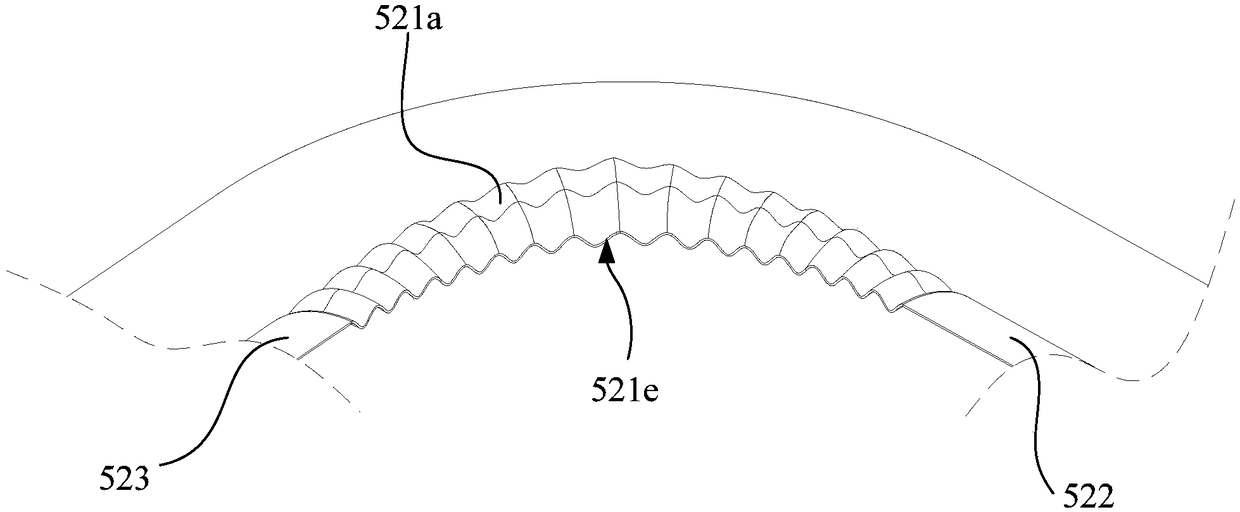
Vibrating diaphragm and loudspeaker

A straight edge and folded ring technology, applied in non-planar diaphragm/paper cone, diaphragm structure, etc., can solve the problems of membrane rupture, affecting the acoustic performance of the speaker, stress concentration, etc., to reduce the diaphragm rupture and and/or delamination, improved reliability and acoustic performance, enhanced diaphragm strength

Active Publication Date: 2018-11-27
GOERTEK INC
View PDF9 Cites 7 Cited by
  • Summary
  • Abstract
  • Description
  • Claims
  • Application Information

AI Technical Summary

Problems solved by technology

However, in the design of the diaphragm, if there is stress concentration, it is easy to cause the diaphragm to break
For example, in the current common design scheme with double rows of patterns on the diaphragm ring part, refer to Figure 5 , stress concentration is prone to occur at the junction of double-row patterns, especially at the corners. In the design scheme with single-row patterns on the diaphragm ring, refer to Image 6 , Stress concentration is also prone to occur at the bottom of the depression of the pattern, especially at the bottom of the most corner of the pattern. The cause of the stress concentration phenomenon, refer to Figure 7 , Figure 8 The cross-sectional view of the pattern in the circle along the direction of the ring part. The cross-sectional views of the two patterns are similar. In the case of no pattern, the cross-section of the corner area of ​​the ring part will be a straight line or a straight line. In the case of a pattern, a plurality of depressions are formed on the straight line of the cross section, and the final cross section is a half-wave structure composed of a straight line segment and a concave curve. The difference between the straight line segment and the concave curve is large, resulting in stress concentration.
In the case of these two pattern designs, the maximum stress can reach 15-20Mpa. In these areas, the reliability of the diaphragm will be affected due to stress concentration, and it is easy to cause membrane rupture or delamination. Affects the acoustic performance of loudspeakers

Method used


Image

  • Vibrating diaphragm and loudspeaker
  • Vibrating diaphragm and loudspeaker
  • Vibrating diaphragm and loudspeaker

Examples


Embodiment Construction

[0039] The following will clearly and completely describe the technical solutions in the embodiments of the present invention with reference to the accompanying drawings in the embodiments of the present invention. Obviously, the described embodiments are only part of the embodiments of the present invention, not all of them. Based on the embodiments of the present invention, all other embodiments obtained by persons of ordinary skill in the art without creative efforts fall within the protection scope of the present invention.

[0040] It should be noted that if there is a directional indication (such as up, down, left, right, front, back...) in the embodiment of the present invention, the directional indication is only used to explain the position in a certain posture (as shown in the accompanying drawing). If the specific posture changes, the directional indication will also change accordingly.

[0041]In addition, if there are descriptions involving "first", "second" and s...


PUM


Abstract

The invention discloses a vibrating diaphragm and loudspeaker, wherein the vibrating diaphragm includes an intermediate part and a folding ring part surrounding the periphery of the intermediate part,the folding ring part includes a first straight side part, a second straight side part, and an arc-shaped corner part connecting the first straight side part and the second straight side part, the arc-shaped corner part and end parts of the first straight side part and the second straight side part which are connected with the arc-shaped corner part form a corner area; a pattern is arranged on the corner area, the pattern extends in an up-down undulating shape along a surrounding direction of the folding ring part in the position of the pattern and has a plurality of crest lines and trough lines, the cross section of the pattern along the surrounding direction of the folding ring part in the position of the pattern is arranged to be a continuously bent smooth curve, and the smooth curve has a plurality of crest lines and trough lines. Through the technical scheme of the invention, the stress concentration phenomenon of the folding ring part of the vibrating diaphragm can be reduced and the performance reliability and acoustic performance of the loudspeaker can be improved.

Description

technical field [0001] The invention relates to the field of electroacoustic technology, in particular to a vibrating membrane and a loudspeaker. Background technique [0002] At present, with the development of the use of loudspeakers, especially mobile phone smart-pa, etc., the loudspeakers are required to be used under the condition of large amplitude and to ensure the reliability of performance at the same time. In the design of the speaker, the design of the diaphragm is very critical, and its design has a great impact on the total harmonic distortion, listening and reliability of the product. However, in the design of the diaphragm, if stress concentration occurs, it is easy to cause rupture of the diaphragm. For example, in the current common design scheme with double rows of patterns on the diaphragm ring part, refer to Figure 5 , stress concentration is prone to occur at the junction of double-row patterns, especially at the corners. In the design scheme with sing...

Claims


Application Information

Patent Timeline
Patent Type & Authority Applications(China)
IPC IPC(8): H04R7/14
CPCH04R7/14
Inventor 郭翔王海荣
Owner GOERTEK INC
Why Eureka
Try Eureka